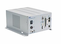
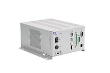
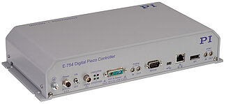
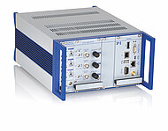
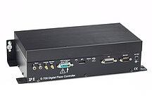
E-712 Digital Piezo Controller
Modular Controller for up to 6 Axes for Highest Precision
- Up to 50 kHz servo update rate
- Highly stable 20-bit D/A converter
- Real-time operating system for excellent trajectory control
- Autoloading of calibration data from stage ID chip for interchangeability of controller and mechanics
- Flexible interfaces: TCP/IP, USB, RS-232; optional broadband analog inputs and outputs
- Extensive software package


Digital linearization for the highest accuracy
Linearization algorithms based on higher-order polynomials reduce the linearity error to less than 0.01 %. That is typically 10 times better than conventional controllers.
Fast periodic motion and data recording
During fast periodic motion, such as that typical for scanning applications, it is possible to increase the tracking accuracy by up to a factor of three using Dynamic Digital Linearization (DDL). The integrated wave generator can save and output periodic motion profiles. Preconfigured sine and triangle wave profiles are provided to support the user when defining the curve, but any user-defined waveforms are possible. Flexible configuration of the data recorder allows recording of the corresponding data.
Flexible analog inputs and real-time PIO
Each of the four optionally available analog inputs can be configured in two ways. As control input, the voltage applied is linked to one of the axes, e.g., for target values. Configuration as external sensor input allows reading of additional sensor signals, e.g., for autofocusing. Alternatively, the controller can be equipped with a fast 32-bit PIO (parallel I/O) for commanding. The PIO supports a restricted command set with 100,000 read and write commands per second required for motion.
Easy system connection
All parameters can be set and checked via software. Easy startup and system configuration can be done via the PIMikroMove utility program, which is in the scope of delivery. Connection to the customer's software is possible via LabView drivers and DLLs. System programming is identical for all PI controllers – combined control of a variety of different controllers is therefore possible without any problems.
Modular design
PI offers preconfigured controllers for 3- and 6-axis operation. Moreover, customers can put controllers together exactly as required. For this purpose, various types of housings and modules as well as additional accessories are available:
- E-712.R1, E-712.R3: 9.5" / 19" chassis for piezo voltages to 135 V, 3 to 6 axes
- E-712.R2, E-712.R4: 19" / 9.5" chassis for piezo voltages to ±250 V, 3 to 6 axes
- E-712.R5: Universal housing 19" 4 HE with CPCI bus
- E-712.M1, E-712.N1: Digital processor and interface modules, TCP/IP, USB, RS-232 interface
- E-711.AL4P, E-711.AL41: High-power amplifier modules, 4 channels, 8 W, -30 V to +135 V
- E-711.AM4, E-711.AM5, E-711.AM6: Amplifier modules for NEXLINE®, -250 to +250 V
- E-711.AM5A, E-711.AM5B: Amplifier modules for NEXLINE®, -250 V to +250 V, for drives with sensor
- E-711.AN4, E-711.AN40: Amplifier modules for NEXACT®
- E-711.C82: DC motor driver module, 2 axes
- E-711.SA3, E-711.SA6: Modules for incremental sensors
- E-711.SS3: Module for strain gauge sensors
- E-711.SC3H, E-711.SE3: Modules for capacitive sensors
- E-711.S3XC, E-711.0ET, E-711.0ET0: Digital sensor signal transmission, capacitive sensors
- E-711.0ATS: Sensor box for digital sensor signal transmission, for sensors with BiSS interface
- E-711.IA4: Analog interface module, 4 inputs and outputs
- E-711.IP: PIO interface module for fast data exchange
- E-711.iS3, E-711.iS6: SPI interface modules
- E-711.SAP, E-711.SAH, E-711.SAN: Sensor signal distributors for incremental sensors
- E-711.SAX, E-711.SAX1, E-711.SAX2, E-711.SAX5: Cables between digital piezo controller and sensor signal distributor
Specifications
Specifications
E‑712.3CD, E-712.3CDA | E‑712.6CD, E-712.6CDA | |
|---|---|---|
Function | Modular digital controller for multi-axis piezo nanopositioning systems with capacitive sensors | Modular digital controller for multi-axis piezo nanopositioning systems with capacitive sensors |
Axes | 3 | 6 |
Processor | PC-based, 600 MHz, real-time operating system | PC-based, 600 MHz, real-time operating system |
Sampling rate, servo control | 50 kHz | 20 kHz |
Sampling rate, sensor | 50 kHz | 20 kHz |
Interfaces and operation | E‑712.3CD, E-712.3CDA | E‑712.6CD, E-712.6CDA |
|---|---|---|
Communication interfaces | TCP/IP, USB, RS-232, SPI | TCP/IP, USB, RS-232, SPI |
Piezo / sensor connector | Sub-D Mix 25W3 | Sub-D Mix 25W3 |
Analog inputs | E-712.3CD: None E-712.3CDA: LEMO: 4 × ±10 V differential; bandwidth: max. 25 kHz; resolution: 18 bit; max. impedance: 250 Ohm | E-712.6CD: None E-712.6CDA: LEMO: 4 × ±10 V differential; bandwidth: max. 25 kHz; resolution: 18 bit; max. impedance: 250 Ohm |
Analog outputs | E-712.3CD: None E-712.3CDA: LEMO: 4 × ±10 V differential; bandwidth: max. 25 kHz; resolution: 16 bit | E-712.6CD: None E-712.6CDA: LEMO: 4 × ±10 V differential; bandwidth: max. 25 kHz; resolution: 16 bit |
Digital inputs/outputs | MDR20: 8 × TTL | MDR20: 8 × TTL |
Command set | PI General Command Set (GCS) | PI General Command Set (GCS) |
User software | PIMikroMove | PIMikroMove |
Application programming interfaces | API for C / C++ / C# / VB.NET / MATLAB / Python, drivers for NI LabVIEW | API for C / C++ / C# / VB.NET / MATLAB / Python, drivers for NI LabVIEW |
Supported functions | Wave generator, trigger I/O, macros | Wave generator, trigger I/O, macros |
Indicators | LEDs for OnTarget, Err, Power, Over Temp | LEDs for OnTarget, Err, Power, Over Temp |
Linearization | 4th-order polynomials, DDL option (Dynamic Digital Linearization) | 4th-order polynomials, DDL option (Dynamic Digital Linearization) |
Miscellaneous | E‑712.3CD, E-712.3CDA | E‑712.6CD, E-712.6CDA |
|---|---|---|
Operating temperature range | 5 to 40 °C | 5 to 40 °C |
Overheat protection | Max. 75 °C, deactivation of the voltage output | Max. 75 °C, deactivation of the voltage output |
Mass | E-712.3CD: 5.35 kg E-712.3CDA: 5.53 kg | E-712.6CD: 5.78 kg E-712.6CDA: 5.96 kg |
Dimensions | 9.5" housing, 236 mm × 132 mm × 296 mm + handles (47 mm length) | 9.5" housing, 236 mm × 132 mm × 296 mm + handles (47 mm length) |
Max. power consumption | 225 W | 225 W |
Operating voltage | 100 to 240 VAC, 50 to 60 Hz | 100 to 240 VAC, 50 to 60 Hz |
Housing types | E-712.R1 / E-712.R3 | E-712.R2 / E-712.R4 | E-712.R5 |
|---|---|---|---|
Function | Chassis with power adapter | Chassis with power adapter | Chassis with cPCI bus |
Piezo voltage range | -30 to 135 V | -250 to 250 V | up to -250 to 250 V |
Channels | 3 to 6 | 3 to 6 | up to 12 |
Dimensions | E-712.R1: 9.5" (236 mm × 132 mm × 296 mm + handles (47 mm length)) E-712.R3: 19" (450 mm × 132 mm × 296 mm + handles (47 mm length)) | E-712.R2: 19" (450 mm × 132 mm × 296 mm + handles (47 mm length)) E-712.R4: 9.5" (236 mm × 132 mm × 296 mm + handles (47 mm length)) | 19" (450 mm × 177 mm × 375 mm + handles (47 mm length)) |
Mass | .R1: 4.16 kg / .R3: 6.7 kg | .R2: 6.7 kg / .R4: 4.16 kg | 4.4 kg |
Operating voltage | 100 to 240 VAC, 50-60 Hz | 100 to 240 VAC, 50-60 Hz | 100 to 240 VAC, 50-60 Hz |
Line power fuses | 2 × T2.5AH, 250 V** | 2 × T2.5AH, 250 V** | 2 × T3.15AH, 250 V** |
Current consumption, max. | 225 VA | 225 VA | 450 VA |
Max. output power | 100 W | 100 W | 200 W |
Master modules | E-712.M1 | E-712.N1 |
|---|---|---|
Function | Digital processor and interface module | Digital processor and interface module |
Supported drive type | Piezo nanopositioning systems (except PiezoWalk® systems) | Piezo nanopositioning systems, PiezoWalk® systems |
Axes | up to 16 | up to 16 |
Sampling rate, servo control | max. 50 kHz | max. 50 kHz |
Sampling rate, sensor | max. 50 kHz | max. 50 kHz |
Communication interfaces | TCP/IP, USB, RS-232, SPI | TCP/IP, USB, RS-232, SPI |
Amplifier/driver | E-711.AL4P / E-711.AL41 | E-711.AM4 / E-711.AM5 / E-711.AM6 / E-711.AM5A / E-711.AM5B | E-711.AN4 / E-711.AN40 | E-711.C82 |
|---|---|---|---|---|
Function | Amplifier module | Amplifier module | Amplifier module | Driver module |
Drive type | Piezo actuators | NEXLINE® | NEXACT® | DC motors |
Channels | 4 | 4 | 4 | 2 |
Average output power per channel | 8 W | 15 W | 4 W | 30 W |
Output voltage | -30 to 135 V | -250 to 250 V | -10 to 45 V | 0 to 24 V |
Sensor input | -- | E-711.AMx: -- E-711.AM5A: incremental, sin/cos E-711.AM5B: absolute, BiSS | -- | Incremental: A/B, sin/cos Absolute: BiSS |
Connector | E-711.AL4P: via E-711.SS3 or E-711.SC3H E-711.AL41: Sub-D 25W3 | E-711.AM4: Sub-D 24W7 E-711.AM5: Sub-D 25 (f) E-711.AM6: Via the HD Sub-D 50 (f) of the E-712.R5 chassis E-711.AM5A / .AM5B: Sub-D 25 (f) | E-711.AN4: Sub-D 15 (f) E-711.AN40: Via the HD Sub-D 78 (f) of the E-712.R5 chassis | Sub-D 15 (f) |
I/O: Sensor modules | E-711.SA3 / E-711.SA6 | E-711.SS3 | E-711.SC3H / E-711.SE3 |
|---|---|---|---|
Function | Module for incremental sensors | Module for strain gauge sensors | Module for capacitive sensors |
Sensor type | Incremental sensors (analog sin/cos, Vpp) | Strain gauge sensors, temperature sensors | E-711.SCH3: capacitive 2-electrode sensors E-711.SE3: PISeca capacitive 1-electrode sensors |
Channels | 3 / 6 | 4 | 3 |
Sensor connector | 1 × / 2 × HD Sub-D 26 (m) | Sub-D 37 (f) | Sub-D 25W3 / 3 × Lemo triaxial socket |
Sensor bandwidth | 300 kHz | 10 kHz | 10 kHz / 5 kHz |
A/D resolution | Interpolation factor selectable | 18 bits (interpolated) | 18 bits (interpolated: 20 bits) |
I/O: Sensor signal transmission | E-711.S3XC | E-711.0ET / E-711.0ET0 | E-711.0ATS |
|---|---|---|---|
Function | Set for digital sensor signal transmission, consisting of: Interface module, sensor box with signal processing electronics | Set for digital sensor signal transmission, consisting of: Interface module, sensor box with signal processing electronics; E-711.0ET additionally with sensor cable | Sensor box for digital sensor signal transmission |
Sensor type | Capacitive 2-electrode sensors | PISeca capacitive 1-electrode sensors | Absolute-measuring or incremental encoders via 32-bit BiSS interface |
Channels | 3 | 3 | 8 |
Sensor connector | Sub-D 25W3 | 3 × Lemo triaxial socket | 8 × Sub-D 9 (f) |
Sensor bandwidth | 10 kHz | max. 5 kHz | N/A |
A/D resolution | 18 bits (interpolated: 20 bits) | 20 bits interpolated | N/A |
I/O: Interface modules | E-711.IA4 | E-711.IP | E-711.iS3 / E-711.iS6 |
|---|---|---|---|
Function | Analog interface module | Parallel input/output interface module for fast data exchange | SPI master interface module |
Input/output | 4 × analog input 4 × analog output | Parallel input/output | SPI |
Channels | 4 | 15 | 3 / 6 |
Resolution | Input: 18 bit Output: 16 bit | 32-bit | 32-bit |
Bandwidth | Input: max. 25 kHz Output: max. 12 kHz | N/A | N/A |
Connector | 8 × LEMO EPG.00.302.NLN | HD Sub-D 62 (f) for connecting to a digital interface card of the PC via the cable included (K040B0121) | Display port |
Downloads
Datasheet
Documentation
Technical Note A000T0074
Guide to Grounding and Shielding
User Manual PZ195
E-711, E-712 Modular Digital Multi-Channel Piezo Controller System
Commands Manual PZ233
GCS Commands for E-711, E-712 Modular Digital Multi-Channel Piezo Controller System
User Manual E712T0010
E-712 Digital Piezo Controller System for PiezoWalk® Drives
User Manual E712T0016
Fast Multi-Channel Photonics Alignment of Silicon Photonics Components with F-712 Alignment Systems and Hexapods from PI. PILightning Option for First Light Search
User Manual E712T0011
E-712 Hexapod Firmware
User Manual E711T0001
E-711.IP Parallel Input/Output Interface (PIO) Module
Software Files
C-990.CD1 Releasenews
PI Software Suite C-990.CD1
General Software Documentation
User Manual A000T0075
Implementing a C-887 PI Controller in TwinCAT 3.1
Software Manual SM159
PIFRF-Analyzer
Software Manual SM157
PIPython - Programming PI Controllers with Python
User Manual A000T0028
Updating PI Software with PIUpdateFinder
Software Manual SM146
GCS Array Data Format
Software Manual SM148
PIMikroMove
Software Manual SM151
PI GCS DLL
Software Manual SM155
PI MATLAB Driver GCS 2.0
Software Manual SM158
PI GCS2 Driver Library for NI LabVIEW
Technical Note A000T0089
PI Software on ARM-Based Platforms
User Manual SM163
PIVirtualMove. Simulation program for parallel-kinematic multi-axis systems
User Manual SM164
Updating controller firmware with PIFirmwareManager
Quote / Order
Ask for a free quote on quantities required, prices, and lead times or describe your desired modification.


