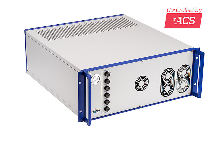
G-901 Motion Controller for High Power Requirement
Integrated Driver for up to 4 Drive Axes with AC Servo Motor, DC Motor, Voice Coil Motor, Stepper Motor
- ACS motion controller with integrated ACS driver and integrated module for safe torque off (STO)
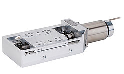
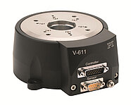
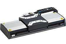
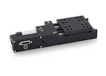
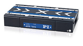
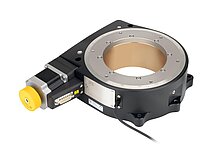
- Directly compatible with positioners from PI
- For AC servo motors / brushless DC motors, brushed DC motors, voice coil motors, stepper motors
- Output power per axis to 1500 W
- Many options for trajectory planning
- Upgradable to up to 8 axes in an ACS EtherCAT network
Overview
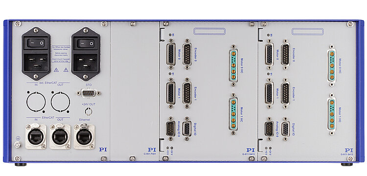
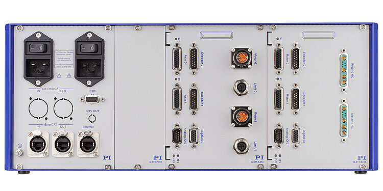
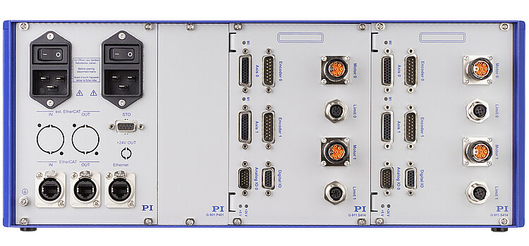
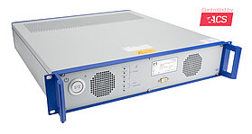
The G-901 motion controllers offer a fully integrated electronics solution with controller and driver in an industry-compatible 19" housing. The G-901 motion controller features the state-of-the-art ACS SPiiPlusEC motion controller and EtherCAT master. Integrated drivers for 2, 3, or 4 axes. Upgradable via EtherCAT to up to 8 synchronized axes (additional driver modules necessary). EtherCAT cycle and generation rate of the motion profile 2 kHz. Ethernet velocity of up to 1 GbE. Servo algorithms for advanced gantry and dual-loop control. STO safety function for safely switching off the power supply for the axes.
Encoder
Supports incremental encoders (sine/cosine or RS-422) and absolute encoders (EnDat 2.2 & 2.1, Smart-Abs, Panasonic, BiSS-A/B/C (SSI)). Depending on the application, the encoders can be led to different interfaces.
I/O lines
The digital inputs and outputs can be flexibly configured. For the evaluation of reference switches, digital inputs can alternatively be led to the motor connectors. Depending on the application, the inputs for the limit and reference switches can be configured for 5 V or 24 V and also as PNP or NPN inputs. Position synchronous trigger signals with up to 10 Mhz output frequency enable a precise process control at high travel velocities (position event generator – PEG).
Communication, software support
The motion controller works as master in an internal EtherCAT network. The open network architecture also enables the integration of components from other manufacturers. For communication with a PC, the motion controller is equipped with an Ethernet TCP/IP and a RS-232 interface. ACS SPiiPlus MMI Application Studio, a modern user software with tools for control tuning and visualizing is included in the scope of delivery. Programming libraries are available for C/C++, COM, .NET, and MATLAB.
Configuration
If the types of positioner are specified when ordering, all connectors of the G-901 are suitably preconfigured at delivery. The default factory configuration, without positioner-specific adjustments, is detailed in the specifications. For subsequent adjustments, please contact our service department.
Specifications
Specifications
G-901.Rx19 / G-901.Rx197 / G-901.Rx199 | |
|---|---|
Function | ACS SPiiPlusEC controller wit up to two ACS UDMcb driver modules including ACS components for STO x codes the intermediate circuit voltage (48 V / 96 V), for details see "Electrical properties" |
Version | 19" rack mount with connectors for positioners from PI |
Motor types | 2 and 3-phase AC servo motors / brushless DC motors, brushed DC motors, voice coil motors, stepper motors |
Number of drive axes | 2 / 3 / 4 Upgradable via EtherCAT with additional driver modules to up to 8 synchronized axes. |
Motion and control | G-901.Rx19 / G-901.Rx197 / G-901.Rx199 |
|---|---|
Controller type | Cascading PIV controller structure with velocity and acceleration feedforward control |
Sampling rate current control | 20 kHz |
Control algorithms | Multiple Input Multiple Output (MIMO) gantry control, dual loop control |
Motion profiles/trajectory planning | Multi-axis point-to-point, jog, tracking, and sequential multi-point motion Multi-axis segmented motion with look-ahead Arbitrary path with PVT cubic interpolation Third order profiles (S-Curve) Smooth on-the-fly change of target position or velocity Inverse/forward kinematics and coordinate transformations (at application level) Master-slave with position and velocity locking (electronic gear/cam) |
Encoder | 1 × per integrated axis, supported types: Incremental: 1Vss, RS-422 Absolute: EnDat 2.2 & 2.1, Smart-Abs, Panasonic, BiSS-A/B/C (SSI) |
Limit switches | 2 × per integrated axis Default: 5 V sinking (NPN) Optional configuration: 24 V; sourcing (PNP) |
Reference switch | Default: 1 × per integrated axis, 5 V sinking (NPN) Optional configuration: 24 V; sourcing (PNP); use as digital multipurpose inputs on digital I/O connector (HD D-sub 15 (f)) |
Motor brake | 1 × per integrated axis Integrated PWM brake driver with current reduction for a reduced heating up of the brake |
Functional safety | STO For safety applications including SIL-3 safety integrity level according to: EN/IEC 61800-5-2 Ed. 2 (Second Environment) EN/IEC 61800-5-1 IEC 61508 IEC 62061 PLe performance level and category 3 according to: EN ISO 13849-1/-2 |
Electrical properties | G-901.R319[x] | G-901.R4197, G-901.R4199 | G-901.R519[x] |
|---|---|---|---|
Intermediate circuit voltage | All axes: 48 V | Axes 0, 1: 96 V Axes 2, 3: 48 V (Axis 3 only with G-901.R4199) | All axes: 96 V |
Output power intermediate circuit, continuous / peak | 1000 W / 1050 W (max. 5 s) | Intermediate circuit 96 V: 2000 W / 2100 W Intermediate circuit 48 V: 480 W / 580 W (max. 10 s) | 2000 W / 2100 W (max. 5 s) |
Output power per axis (effective value), continuous / peak (max. 1 s)* | 250 W / 740 W | Axes 0, 1: 500 W / 1500 W (at 96 V intermediate circuit voltage) Axes 2, 3: 250 W / 580 W (at 48 V intermediate circuit voltage; axis 3 only with G-901.R4199) | 500 W / 1500 W |
Current limitation per motor phase (amplitude of sine), continuous/peak (max. 1 s) | 6.6 A / 20 A | 6.6 A / 20 A | 6.6 A / 20 A |
Interfaces and operation | G-901.Rx19[x] |
|---|---|
Motor connectors per driver module with 48 V intermediate circuit voltage** | 2 × HD D-sub 26 (f), maximum 3 A continuous current per pin 2 × D-sub 9W4 (f), maximum 20 A per motor phase Alternative use is possible, depending on maximum phase current. The lines for limit and reference switches are available on all connectors. The lines for motor brakes are available on the HD D-sub 26 (f) connectors. |
Motor connectors per driver module with 96 V intermediate circuit voltage** | 2 × M15 9-pin (f) The lines for limit switches are available for: 2 × HD D-sub 26 (f) 2 × M12 5-pin (f) 2 × D-sub 15 (m) The lines for reference switches are available on the HD D-sub 26 (f) connectors. The lines for motor brakes are available on the M15 9-pin (f) and HD D-sub 26 (f) connectors. |
Sensor connectors, per driver module** | 2 × D-sub 15 (m) 2 × HD D-sub 26 (f) Alternative use depending on encoder type. Default factory configuration at delivery: Digital incremental encoder (RS-422) or absolute encoder on HD D-sub 26 (f) Incremental encoder 1 Vss on D-sub 15 (m) Possible modified factory configuration at delivery: Digital incremental encoder (RS-422) or absolute encoder on D-sub 15 (m) |
Digital I/O lines, per driver module | HD D-sub 15 (f): 2 × outputs PNP 24 V source; also control the drivers for the motor brakes Default for inputs: 2 × PNP 24 V source on HD D-sub 15 (f); in addition 2 × NPN 5 V sinking for reference switches on the motor connectors Optional configuration for inputs: 4 × PNP 24 V source on HD D-sub 15 (f) |
Analog I/O lines, per driver module | HD D-sub 15 (m): 2 differential analog inputs: ±10 V, 12-bit 2 differential analog outputs: ±10 V, 10-bit |
Outputs for position event trigger (PEG), per driver module | Parallel on HD D-sub 15 (m) and HD D-sub 15 (f): 2 differential outputs (RS-422) for pulses at programmable positions, pulse width 26 ns to 1.75 ms, max. 10 MHz; only possible with incremental encoder |
Inputs for STO safety function | D-sub 9 (f) 2 differential inputs (STO1, STO2): 24 V, < 50 mA per pin If at least one signal assumes the "low" state, all drives are deactivated at the same time within 50 to 200 ms. |
EtherCAT network | Up to 8 axes in an ACS EtherCAT network, also using EtherCAT third-party components. |
Control rate and EtherCAT clock rate | 2 kHz |
Communication interfaces | EtherCAT IN and OUT: RJ-45 Ethernet (TCP/IP, Modbus/TCP, EtherNet/IP): RJ-45 RS-232: D-sub 9 (m) |
User software | ACS SPiiPlus MMI Application Studio |
Application programming interfaces | Programming libraries for C/C++, COM, .NET, MATLAB available |
Programming | ACSPL+ real-time scripting language: Up to 10 simultaneously running programs (buffer) |
Miscellaneous | G-901.R319[x] | G-901.R419x | G-901.R519[x] |
|---|---|---|---|
Operating voltage*** | 2 × mains connector 100-250 V AC, 50-60 Hz | 2 × mains connector 100-250 V AC, 50-60 Hz | 2 × mains connector 100-250 V AC, 50-60 Hz |
Required protection per mains connector*** | IEC: 12-16 A @ 250 V AC; 50 Hz UL/CSA: 12-20 A @ 125/250 V AC; 60 Hz | IEC: 12-16 A @ 250 V AC; 50 Hz UL/CSA: 12-20 A @ 125/250 V AC; 60 Hz | IEC: 12-16 A @ 250 V AC; 50 Hz UL/CSA: 12-20 A @ 125/250 V AC; 60 Hz |
Operating temperature range | 5 °C to 40 °C (temperature protection switches off at excessively high temperatures) | 5 °C to 40 °C (temperature protection switches off at excessively high temperatures) | 5 °C to 40 °C (temperature protection switches off at excessively high temperatures) |
Mass | 13 kg | 17 kg | 15.5 kg |
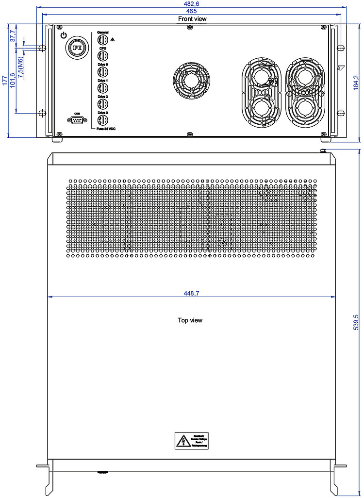
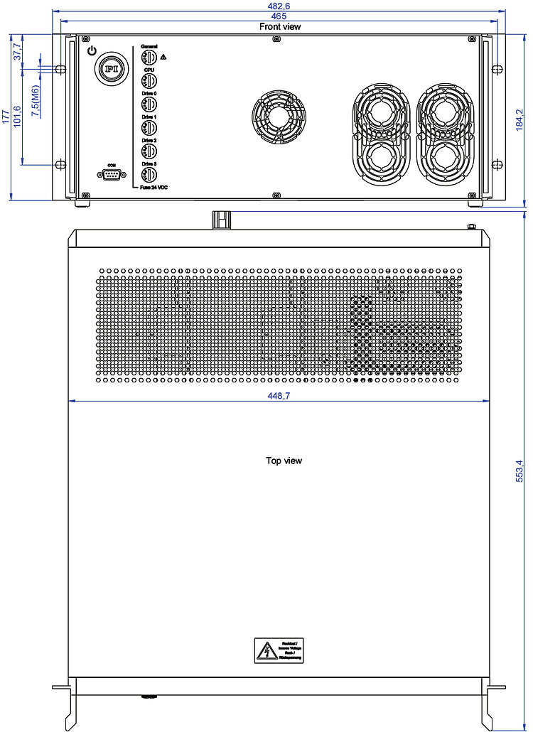
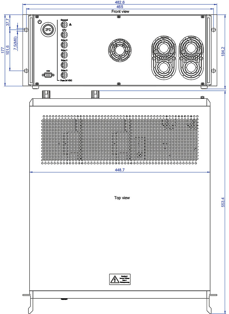
Dimensions | 482.6 mm × 539.5 mm × 184.2 mm (including handles) | 482.6 mm × 553.4 mm × 184.2 mm (including handles) | 482.6 mm × 553.4 mm × 184.2 mm (including handles) |
Downloads
Datasheet
Documentation
User Manual G901M0003
G-901.R519, G-901.R5197, and G-901.R5199 ACS motion controller with 96 V intermediate voltage and interfaces for PI positioners
User Manual G901M0002
G-901.R4197, G-901.R4199 ACS motion controller with 48 V and 96 V intermediate voltage and interfaces for PI positioners
User Manual G901M0001
G-901.R319, G-901.R3197, and G-901.R3199 ACS motion controller with 48 V intermediate voltage and interfaces for PI positioners
Short Instructions MS256
ACS Motion Controllers and Drivers: G-900, G-901, G-902, G-910
3D Models
3-D model G-901.R3199
3-D model G-901.R4199
3-D model G-901.R519
3-D model G-901.R3197
3-D model G-901.R5199
3-D model G-901.R5197
3-D model G-901.R4197
3-D model G-901.R319
Quote / Order
Ask for a free quote on quantities required, prices, and lead times or describe your desired modification.
How to Get a Quote

Questions? - Ask a PI Engineer
Technology

EtherCAT Connectivity of PI Products
PI offers high-precision drives for use as EtherCAT slave, or integrates with ACS Motion Controllers as Master, or 2nd Master in an existing architecture.
Digital Motion Controllers
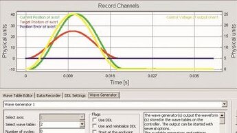
Digital technology opens up possibilities for improving performance in control engineering which do not exist with conventional analog technology.
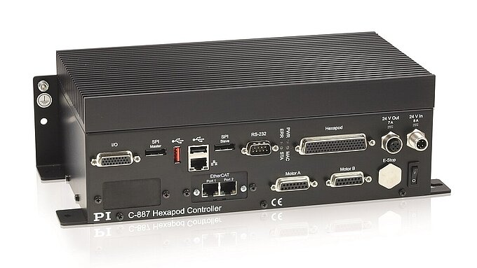
Digital & Analog Interfaces
Fast USB or TCP/IP interfaces as well as RS-232 are the standard interfaces supported by modern digital controllers from PI. Furthermore, PI also provides digital or analog real-time capable interfaces.
