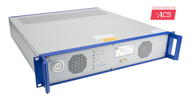
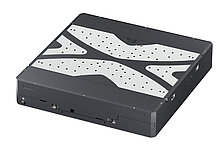
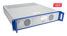
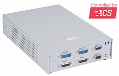
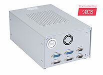
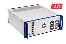
G-902.RxI ACS Driver Module
For 4 Drive Axes with AC Servo Motor, DC Motor, Voice Coil Motor, Stepper Motor
- Universal driver module as benchtop device or control cabinet module
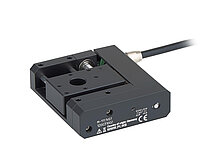
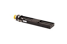
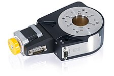
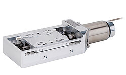
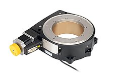
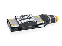
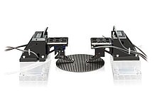
- Directly compatible with positioners from PI
- For AC servo motors / brushless DC motors, brushed DC motors, voice coil motors, stepper motors
- Encoder inputs for incremental and absolute-measuring encoders
- Output power per axis to 363 W
- Integrated module for safe stop 1 (SS1) and safe torque off (STO)
- Many options for trajectory planning
- Communication via EtherCAT
Universal driver module
ACS driver module for the operation of different motor and encoder types, can be configured for a variety of applications. 4 axes, 5 A continuous current per axis possible. 4 motor brakes via PWM brake driver, reduced heat generation of the motor brake. Motion profiles are generated by an external motion controller (not included) and received via EtherCAT.
Encoder
Supports incremental encoders (sine/cosine or RS-422) and absolute encoders (BiSS-C, EnDat 2.1 & 2.2, Smart-Abs, SSI, Sanyo-Denki, Panasonic A6). Depending on the application, the encoders can respectively be led to the motor interface or the separate sensor interface.
I/O lines
The digital inputs and outputs can be flexibly configured. For the evaluation of reference switches, digital inputs can alternatively be led to the motor connectors. Depending on the application, the inputs for the limit and reference switches can be configured for 5 V or 24 V and also as PNP or NPN inputs. Position synchronous trigger signals with up to 10 Mhz output frequency enable a precise process control at high travel velocities (position event generator – PEG).
Communication
Communication with a PC via Ethernet TCP/IP and RS-232 interfaces. EtherCAT interface for the integration into an EtherCAT network. Commanding via EtherCAT master.
Configuration
If the types of positioners used are specified when ordering, all connectors of the G-902 are suitably preconfigured at delivery. The default configuration, without positioner-specific adjustments, is detailed in the specifications. For subsequent adjustments, please contact our customer service department.
Specifications
Specifications
Motion and Control | G-902.R1I001 / G-902.R2I001 |
|---|---|
Sample/Update rate of control loop | 20 kHz position 20 kHz velocity 20 kHz current |
Control algorithms | Cascading PIVFF controller structure with loop-shaping filters Velocity feedforward MIMO (Multiple Input Multiple Output) gantry control algorithm Dual-loop control Disturbance rejection Gain scheduling Field-oriented control Space vector modulation |
Profile generation | 3rd order with uniform endpoint modification during operation |
Encoder | 1 × per axis, supported types: Incremental: 1 Vpp, RS-422 Absolute: BiSS-C, EnDat 2.1 & 2.2, Smart-Abs, SSI, Sanyo-Denki, Panasonic A6 |
Limit switches | 2 × per axis Default: 5 V sinking (NPN) Optional configuration: 24 V; sourcing (PNP) |
Reference switch | Default: 1 × per axis, 5 V sinking (NPN) Optional configuration: 24 V; sourcing (PNP); use as digital multipurpose inputs on digital I/O connector (HD D-sub 15 (f)) |
Motor brake | 1 × per axis Integrated PWM brake driver with current reduction for reduced brake heating |
Functional safety | STO (safe torque off): Electrical interface: two-channel input, 24 V, insulated Safety standards: EN/IEC 61800-5-2 Ed. 2 (second environment) EN/IEC 61800-5-1 IEC 61508 IEC 62061 PLe performance level and category 3 according to: EN ISO 13849-1/-2 SS1 (safe stop 1): Braking time until STO activation: 110-230 ms The exact value for the braking time is a fixed value (SS1-t functionality) and depends on the product configuration. |
Electrical Properties | G-902.R1I001 | G-902.R2I001 |
|---|---|---|
Intermediate circuit voltage | 48 V | 48 V |
Output power intermediate circuit, continuous / peak (max. 10 s) | 550 W / 550 W at 40 °C | 1000 W / 1200 W at 40 °C |
Output power per axis (effective value), continuous / peak (max. 1 s) | 186 W* / 363 W* | 186 W / 363 W |
Current limitation per motor phase (sine amplitude), continuous / peak (max. 1 s) | 5 A / 10 A | 5 A / 10 A |
Interfaces and Operation | G-902.R1I001 / G-902.R2I001 |
|---|---|
Motor connector | 4 × HD D-sub 26 (f) |
Sensor connector | 4 × HD D-sub 26 (f) or via the motor connectors Connector selection per axis via DIP switch |
Digital inputs | Default: 4 × NPN 5 V sinking for reference switches on the motor and encoder connectors Optional configuration: Up to 4 multipurpose inputs, PNP 24 V source, parallel on 2 × HD D-sub 15 (f) |
Digital outputs | 2 × HD D-sub 15 (f): 4 × output PNP 24 V source; used for controlling the brake drivers D-sub 25 (f): 8 × multipurpose output, differential (RS-422) |
Analog inputs / outputs | HD D-sub 15 (m): 2 differential analog inputs: ±10 V, 12 bit 2 differential analog outputs: ±10 V, 10 bit |
Outputs for position event generator (PEG) | Parallel on HD D-sub 15 (m) and HD D-sub 15 (f): 4 differential outputs (RS-422) for pulses at programmable positions, pulse width 27 ns to 1.745 ms, max. 10 MHz; only possible with incremental encoder |
Inputs for STO safety function | D-sub 9 (f): 2 inputs (STO1, STO2): 24 V, up to 50 mA per STO input, with an inrush current of less than 70 mA |
LEDs | Status of the fuses for the 24 V power supply, STO signals, logic supply |
Communication interfaces | EtherCAT IN and OUT: RJ-45 Ethernet (TCP/IP, Ethernet/IP, Modbus/TCP): RJ-45 RS-232: D-sub 9 (m) |
User software | ACS SPiiPlus MMI Application Studio |
Application programming interfaces | Programming libraries for C/C++, COM, .NET, MATLAB available |
Programming | ACSPL+ real-time script language: up to 4 simultaneously running programs (buffers) |
Miscellaneous | G-902.R1I001 / G-902.R2I001 |
|---|---|
Operating voltage | 100-240 V AC, 50-60 Hz |
Required fusing per mains supply line | IEC: 12-16 A at 250 V AC; 50 Hz UL/CSA: 12-20 A at 125/250 V AC; 60 Hz |
Operating temperature range | 5 to 40 °C (temperature protection switches off at excessively high temperatures) |
Mass | 10 kg |
Dimensions | 482.6 mm × 533.75 mm × 95.3 mm (including handles) |
Downloads
Datasheet
Documentation
User Manual G902UM0002
G-902.RxI Drive Modules
Short Instructions MS256
ACS Motion Controllers and Drivers: G-900, G-901, G-902, G-910
Quote / Order
Ask for a free quote on quantities required, prices, and lead times or describe your desired modification.
