|
Function
|
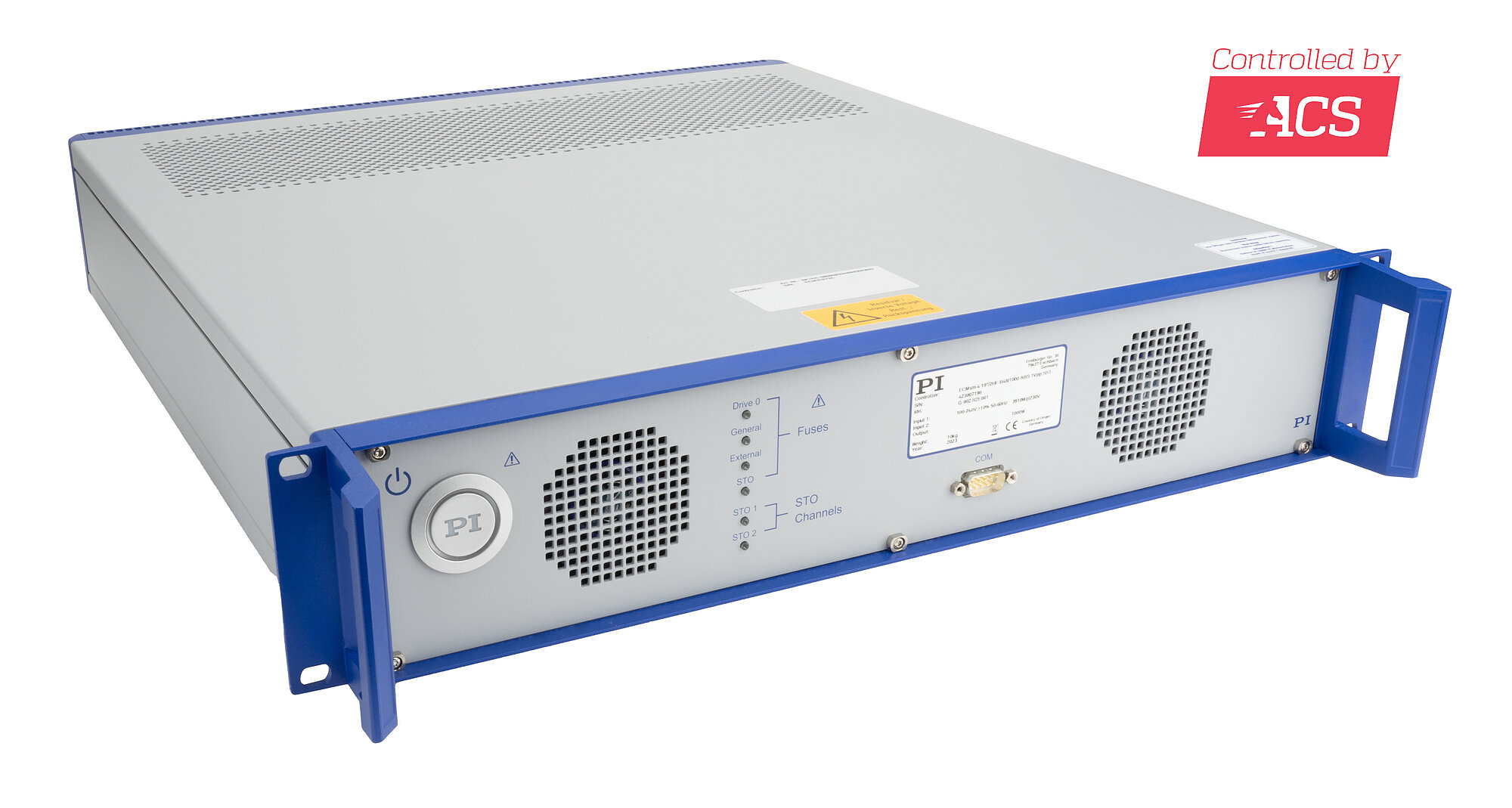
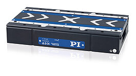
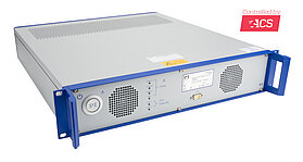
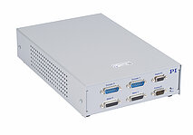
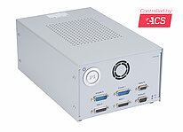
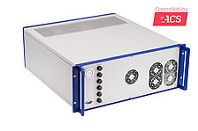
ACS ECMsm controller with integrated servo drives
|
|
|
Design
|
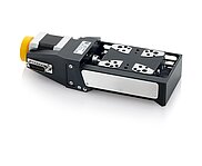
19-inch rack-mount controller with connectors for PI positioners
|
|
|
Motor types
|
2-phase and 3-phase AC servo motors / brushless DC motors, brushed DC motors, voice coil motors, stepper motors
|
|
|
Number of drive axes
|
4
|
2
|
|
|
Motion and control
|
G-902.R1E001 / G-902.R2E001
|
G-902.R1E002
|
|
|
Sample/update rate of control loop
|
20 kHz position20 kHz velocity20 kHz current
|
|
|
Control algorithms
|
Cascaded PIVFF controller structure with loop-shaping filtersVelocity feedforwardMIMO (Multiple Input Multiple Output) gantry control algorithmDual-loop controlDisturbance rejectionGain schedulingField-oriented controlSpace vector modulation
|
|
|
Profile generation
|
3rd order with uniform end-point modification during operation
|
|
|
Encoder
|
1 × per integrated axis, supported types:Incremental: 1 Vss, RS-422Absolute: BiSS-C, EnDat 2.1 & 2.2, Smart-Abs, SSI, Sanyo-Denki, Panasonic A6
|
1 × per integrated axis, supported types:Incremental: 1 Vss, RS-422
|
|
|
Limit switch
|
2 × per integrated axisStandard: 5 V sinking (NPN)Optional configuration: 24 V; sourcing (PNP)
|
|
|
Reference switch
|
Standard: 1 × per integrated axis, 5 V sinking (NPN)Optional configuration: 24 V; sourcing (PNP); use as digital multipurpose inputs on digital I/O connector (HD D-sub 15 (f))
|
|
|
Motor brake
|
1 × per integrated axisIntegrated PWM brake driver with current reduction for reduced brake heating
|
|
|
Functional safety
|
STO (safe torque off):Electrical interface: Two-channel input, 24 V, insulatedSafety standards:EN/IEC 61800-5-2 Ed. 2 (second environment)EN/IEC 61800-5-1IEC 61508IEC 62061Performance Level PLe and category 3 according to:EN ISO 13849-1/-2SS1 (safe stop 1):Braking time until STO activation: 110-230 msThe exact value for the braking time is a fixed value (SS1-t functionality) and depends on the product configuration.
|
|
|
Electrical properties
|
G-902.R1E001
|
G-902.R2E001
|
G-902.R1E002
|
|
Intermediate circuit voltage
|
48 V
|
48 V
|
48 V
|
|
Output power intermediate circuit, continuous/peak (max. 10 s)
|
550 W / 550 W at 40 °C
|
1000 W / 1200 W at 40 °C
|
550 W / 550 W at 40 °C
|
|
Output power per axis (effective value), continuous/peak (max. 1 s)
|
186 W* / 363 W*
|
186 W / 363 W
|
186 W / 363 W*
|
|
Current limitation per motor phase (sine amplitude), continuous/peak (max. 1 s)
|
5 A / 10 A
|
5 A / 10 A
|
5 A / 10 A
|
|
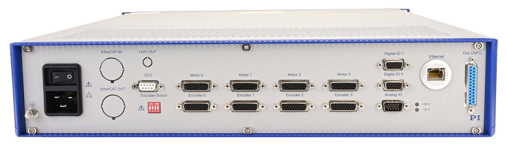
Interfaces and operation
|
G-902.R1E001 / G-902.R2E001
|
G-902.R1E002
|
|
|
Motor connector**
|
4 × HD D-sub 26 (f)
|
2 × HD D-sub 26 (f)
|
|
|
Sensor connector**
|
4 × HD D-sub 26 (f) or via the motor connectorsConnector selection per axis via DIP switch
|
2 × HD D-sub 26 (f) or via the motor connectorsConnector selection per axis via DIP switch
|
|
|
Digital inputs
|
Default:4 × NPN 5 V sinking for reference switches on the motor and encoder connectorsOptional configuration:Up to 4 multipurpose inputs, PNP 24 V source, parallel on 2 × HD D-sub 15 (f)
|
|
|
Digital outputs
|
2 × HD D-sub 15 (f):4 × output PNP 24 V source; used for controlling the brake driversD-sub 25 (f):8 × multipurpose output, differential (RS-422)
|
|
|
Analog inputs / outputs
|
HD D-sub 15 (m):2 differential analog inputs: ±10 V, 12 bit2 differential analog outputs: ±10 V, 10 bit
|
|
|
Outputs for position event generator (PEG)
|
Parallel on HD D-sub 15 (m) and HD D-sub 15 (f):4 differential outputs (RS-422) for pulses at programmable positions, pulse width 27 ns to 1.745 ms, max. 10 MHz; only possible with incremental encoder
|
|
|
Inputs for STO safety function
|
D-sub 9 (f):2 inputs (STO1, STO2): 24 V, up to 50 mA per STO input, with an inrush current of less than 70 mA
|
|
|
LEDs
|
Status of the fuses for the 24 V power supply, STO signals, logic supply
|
|
|
Cycle time of the controller
|
1 kHz
|
|
|
Communication interfaces
|
Ethernet (TCP/IP, Ethernet/IP, Modbus/TCP): RJ-45RS-232: D-sub 9 (m)
|
|
|
User software
|
ACS SPiiPlus MMI Application Studio
|
|
|
Application programming interfaces
|
Program libraries available for C/C++, COM, .NET, MATLAB
|
|
|
Programming
|
ACSPL+ real-time script language: up to 6 simultaneously running programs (buffers)
|
|
|
Environment
|
G-902.R1E001 / G-902.R2E001 / G-902.R1E002
|
|
|
|
Operating voltage
|
100-240 V AC, 50-60 Hz
|
|
|
|
Required fusing per power inlet
|
IEC: 12-16 A at 250 V AC; 50 HzUL/CSA: 12-20 A at 125/250 V AC; 60 Hz
|
|
|
|
Operating temperature range
|
5 to 40 °C (temperature protection switches off at excessively high temperatures)
|
|
|
|
GND
|
10 kg
|
|
|
|
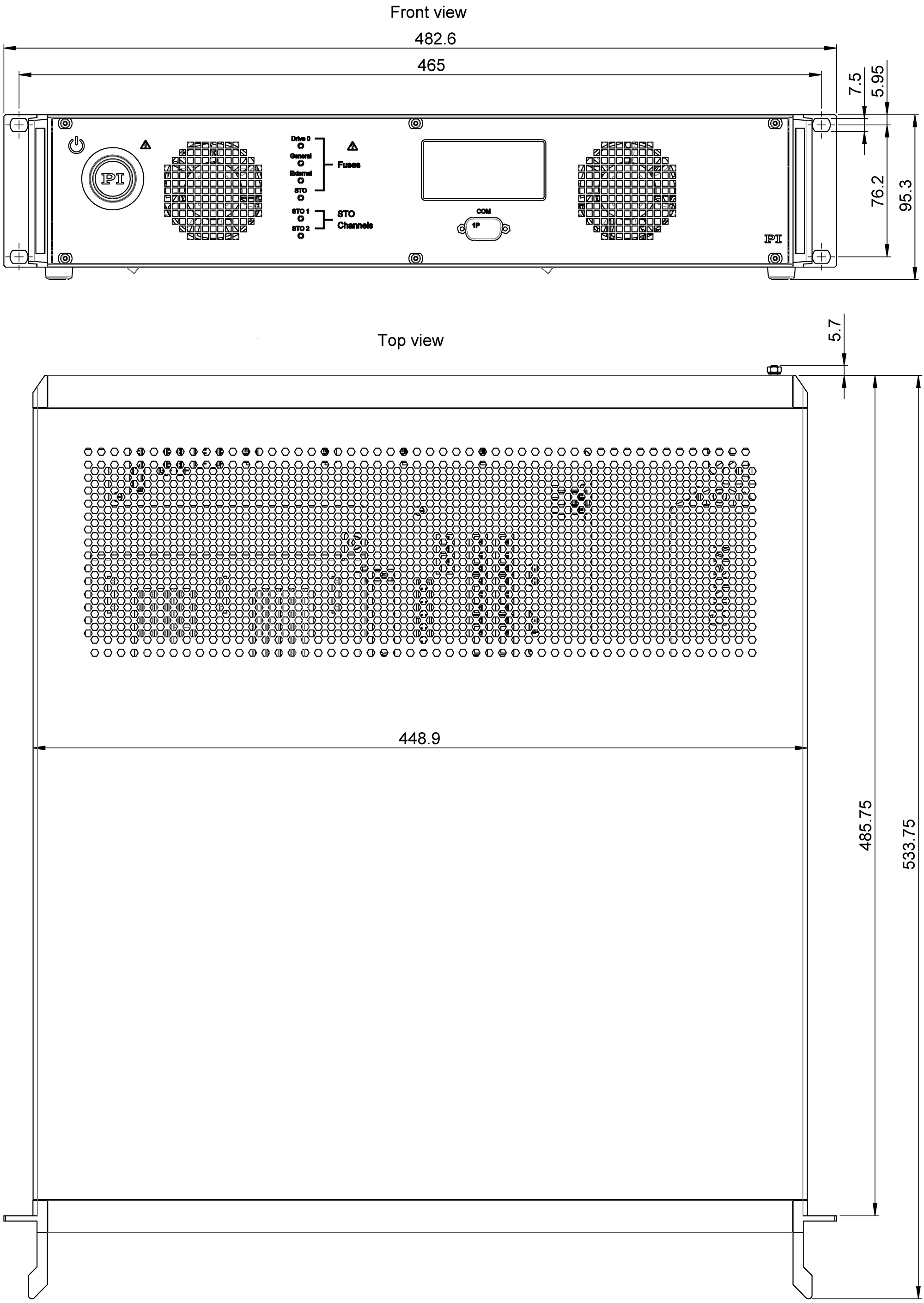
Dimensions
|
482.6 mm × 533.75 mm × 95.3 mm (including handles)
|
|
|