1. Overview
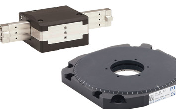
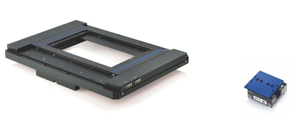
While conventional positioning systems convert the rotary motion of a motor into linear motion using a spindle, PILine® positioning systems are based on a special direct drive. This completely eliminates backlash and play and enhances the response time and positioning accuracy. Furthermore, they offer high-resolution positioning and fast step-and-settle performance.
At the same time, ultraslow motion can be realized with constant velocities down to a few nm per second. This white paper focuses on giving you an overview of the possibilities, and shows you how to make the most of your PILine® linear stages specifically for your application.
2. Operating Principle of PILine® Positioning Systems
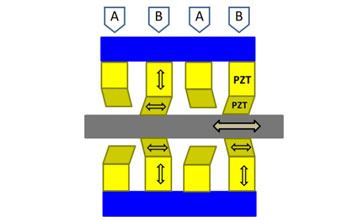
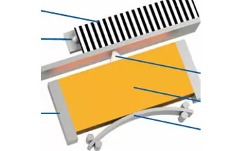
PILine® positioning systems are based on ultrasonic piezomotors that are capable of direct-driven linear motion. A piezoelectric actuator is preloaded against a runner using a coupling element (see Fig. 1).
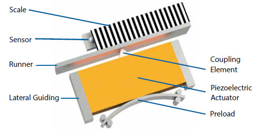
Electrical excitement of the piezoelectric actuator at its resonance frequency1 causes oscillation. Due to the preload, the actuator oscillation is converted to continuous feed motion by the coupling element, which moves the runner.
The preload also causes the drive to self-lock when at rest. The velocity of the motion can be adjusted by modifying the amplitude of the excitation and therefore the amount of power transferred to the runner.
Changes in position of the stage are detected accurately by an incremental, or in some cases, an absolute-measuring linear encoder. The number of counts recorded by the encoder is proportional to the distance travelled. Sub-nm resolution is possible using state-of-the art sensors and gratings.
Note that for accurate reproduction of the sensor resolution, the motor has to be operated in closed-loop mode.
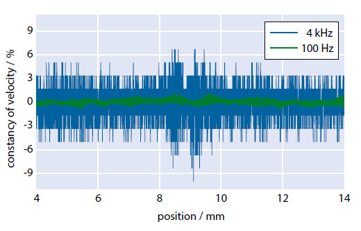
Direct measurement of the velocity is not possible with this method. However, by measuring the time Δt = t2 – t1 required for the stage to travel a distance Δs = s2 – s1, the velocity can be obtained from the relation v = Δs / Δt.
Bear in mind that the distance Δs varies depending on the sampling rate 1/Δt used, therefore different results are obtained for the constancy of velocity (= vactual / vset – 1), despite identical stage movement (see Fig. 2).
Depending on the particular area of application, a customer might be interested that the stage reaches the target destination as fast as possible (at the cost of precision), or as accurately as possible (with reservations on the time required). Both requirements are addressed in detail in the following chapters.
2.1 Stability: Self Clamping Principle
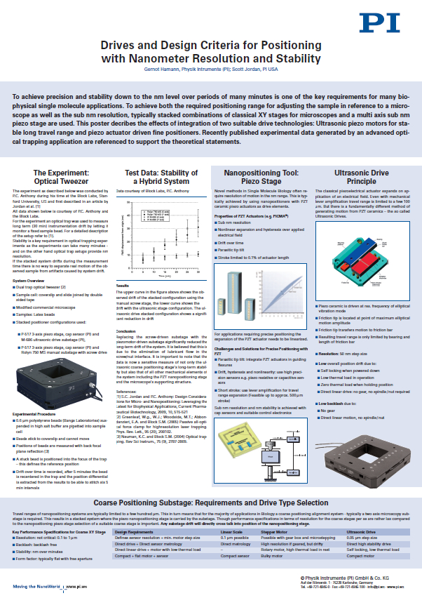
Velocity and resolution are not the only criteria for precision motion control applications. Due to the preload and the ceramic / ceramic drive principle, the ultrasonic motor acts like a brake when not energized. This feature is decisive for applications where long term stability is crucial, for example in super-resolution microscopy and imaging. Tests with ultrasonic motors in an optical trapping set-up show significantly better stability than screw driven stages, especially over long periods of time.
More information is available in the paper below.
3. Fast Positioning
When targeting a position, the inbuilt profile generator of the PILine® controller (e.g. C-867) creates a velocity profile for the motor, which consists of three regions (see Fig. 3): (A) acceleration, (B) constant velocity, and (C) deceleration and settling.
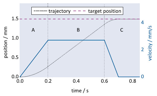
Each of these regions can be tuned individually by adjusting the corresponding controller parameters. For better under- standing, the principles of the servo algorithm will be explained, before discussing individual parameters later in this chapter.
PILine® stages are usually operated in closed-loop mode, where a proportional-integral-derivative (PID) algorithm is used to compensate for trajectory deviations. Comparing the actual position (obtained from the sensor) with the commanded position returns the following error which serves as a process variable for the PID algorithm. Using the constantproportional, integral and derivative PID terms, the controller output is adjusted in an attempt to minimize the following error.
The controller features up to five independent sets of PID parameters (set 0 to 4). As depicted in Fig. 4, these PID sets are arranged concentrically around the commanded position or around the target position (default), depending on the window changing strategy (parameter0x4D).
The proportional, integral and derivative parameters should decrease with increasing PID set number. The number of parameter sets to be used can be configured with parameter 0x400.Operating with three sets is recommended. Each set of PID parameters contains two windows: window enter and window exit, specifying the activation area.
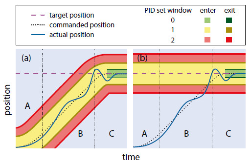
As soon as the actual position of the stage reaches one of the entry windows, the corresponding PID set is activated automatically. By definition, window exit has to be larger than window enter to prevent the parameters from switching back immediately. The window exit parameter of the outermost PID set is ignored by the PILine® controller, leaving this PID set active even when the stage exits the window.
PID parameter set 0 (0x401 to 0x407) plays the specific role of regulating the settling behavior – it is activated only after the commanded trajectory has finished (see Fig. 4). The other PID sets (1 to 4, 0x411 – 0x447) determine the behavior during stage motion.
3.1 Region A: Acceleration
In this region, the stage accelerates until it reaches the maximum velocity predetermined by the profile generator.
The acceleration region can be minimized by
- increasing the acceleration parameter
- adjusting the drive offset parameters
Please note that all of these parameters depend on ambient conditions and have to be determined individually for each area of application.
As a quick and simple first measure, try increasing the motor’s acceleration (0xB), which by default is set to a rather conservative value (see Fig. 5).
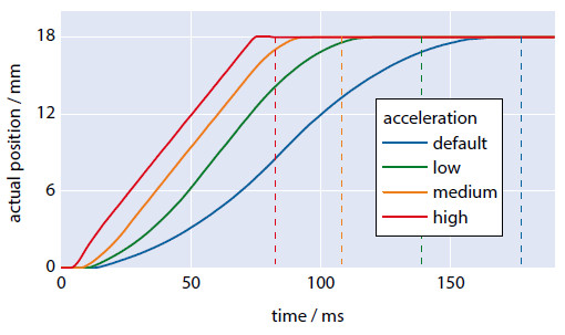
Note that higher acceleration can reduce the product lifetime.
Please make sure to monitor the motor output of the controller: under normal circumstances, the motor should run at a motor output of approximately 50 % of themaximum motor output parameter (0x9). The top 20 % of the motor output is intended as a control reserve. For this reason,avoid operation above a motor output value of 80 % to avoid damaging the motor.
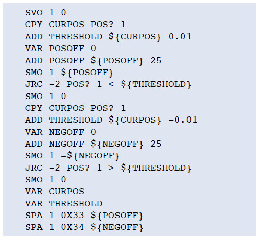
The second method of shortening the acceleration region involves adjusting the offset voltage parameters of the controller. Before the stage can start moving, stiction between the coupling element and runner has to be overcome. For that purpose, the controller gradually increases the motor output. The delay time associated with this process can be reduced by increasing the drive offset parameter (0x48), which sets the start value of the motor output voltage (see Fig. 6).
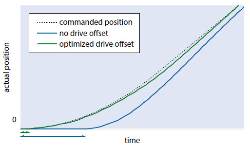
Additionally, compensation for direction-dependent load of the stage (e.g. when mounted vertically), is achieved by tuning the parameters motor offset positive (0x33) and motor offset negative (0x34). These offsets are applied together with the motor drive offset. Suitable initial values can be found and set using the following host macro in PIMikroMove:
3.2 Region B: Constant Velocity
In this region, the stage has reached its constant maximum velocity.
The constant velocity region can be reduced by increasing the stage velocity(parameter 0x49).
In some cases, especially when covering short distances, the stage may go directly from acceleration (region A) to deceleration (region C), without reaching the maximum velocity. If so, try increasing the acceleration (0xB) and deceleration (0xC) parameters.
3.3 Region C: Deceleration and Settling
In this region, the motor decelerates as it approaches the target position.
The deceleration region can be minimized by
- increasing the deceleration parameter
- adjusting the integral term of PID set 2
- increasing window enter of PID set 0
Increasing the deceleration parameter (0xC) is similar to increasing the acceleration in region A, as explained in chapter 3.1.
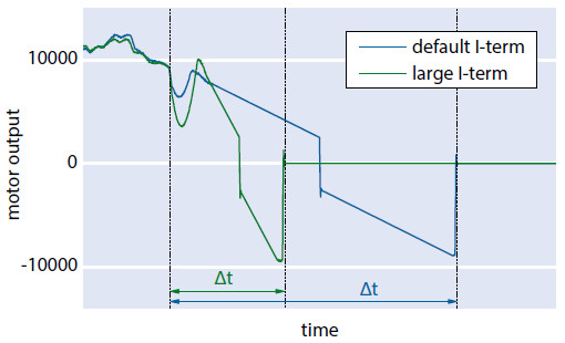
Faster deceleration can also be obtained by increasing the integral term of the second PID set (parameter 0x422). This increases the velocity of pulling the stage into the settling window (PID set 0), as depicted in Fig. 8.
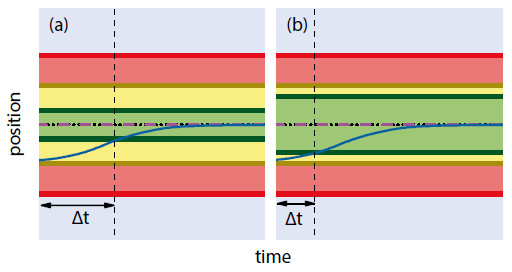
If accuracy is not of utmost importance, the window enter parameter of PID set 0 (referred to as “settling window”, (0x406) can be widened to achieve earlier settling, as shown in Fig. 9.
4. Accurate Positioning
When particularly accurate positioning is required, reservations on positioning speed have to be taken into account. Higher accuracy can be obtained by using a smaller settling window; i.e., by reducing the window enter 0 (0x406) and window exit 0 (0x407)parameters.
The achievable positioning accuracy is limited by the grating period of the scale, the accuracy of the sensor, and the interpolation factor of the sensor electronics. For higher accuracy consider acquiring:
- stages with finer grating periods
- controllers with internal interpolation
As mentioned in chapter 2, a sensor is used (see Fig. 1; also referred to as encoder) to determine the position and velocity of the stage. In PILine® positioning systems, optical and magnetic incremental and absolute sensors can be used depending on the required accuracy, energy consumption and cost efficiency. In most cases, optical incremental sensors are used. These sensors determine the distance to a given reference point by recording a periodic pattern (referred to as grating) on a scale.
The grating periods utilized range from a few to several tens of micrometers. Using two photodiodes with a 90° phase shift, two sinusoidal signals are generated allowing for detection of the direction of motion. These signals are then processed by an interpolation circuit which splits each period into several equally-spaced pulses. The final resolution corresponds to that of the grating period divided by the interpolation factor.
Using a PILine® stage with a state-of-the-art PIOne (PI Optical Nano Encoder) sensor with a sensor signal period of 0.5 μm and an interpolation factor of >1,000, sub-nm resolution can be achieved.
Typically, interpolators with interpolation factors of 256 to 8192 are integrated directly into the stage electronics. Some PILine® stages have a switch for bypassing this inbuilt interpolator. In this case, the output changes from internally interpolated A/B counts to raw sine/cosine signals, which can be processed further by an external interpolator.
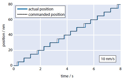
The new PILine® C-867.1U controller features an integrated interpolator with an interpolation factor of up to 20,000, enabling manifold increasing the resolution of your existing stages. Applications that require precise positioning as well as very slow-motion benefit from this gain in resolution (refer to Fig. 10).
5. Controlled Positioning with Priority on the Trajectory
PILine® motors feature a broad dynamic velocity range of 10 nm/s to > 100 mm/s, which can be subdivided into three characteristic ranges:
- Ultraslow motion (10 nm/s to 10 μm/s)
- Slow motion (10 μm/s to 1 mm/s)
- Fast motion (> 1 mm/s)
The peculiarities and challenges of each of those velocity ranges will be discussed in the following subchapters.
5.1 Ultraslow Motion (10 nm/s to 10 μm/s)
Positioning at ultraslow speeds is essential when scanning small objects; e.g., when using a microscope with a PILine® stage in manual mode. Customizing the PID and controller parameters according to the intended use is imperative for achieving optimum performance of the stage.
A key requirement for this velocity range is uniform motion. For this purpose, some PILine® controllers (e.g., the C-687.262) offer a so-called second phase actuation. In this mode, the unused electrode of the motor is driven by a secondary output stage; the amplitude can be set using the motor offset parameter (0x6F). Doing so will adjust the forward feed vector of the coupling element, which decreases the breakaway torque.
On the downside, forward force is reduced in this mode. The best results are achieved using motor offset values between 50 % and 70 % of the maximum motor output parameter (0x9).
Following errors, which occur particularly in this velocity range, have to be compensated by boosting the P-term of the current PID set to a very high value (refer to chapter 6). Assuming that the stage is well tuned, the actual trajectory can closely reproduce the generated profile as depicted in Fig. 11.
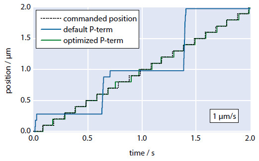
PILine® controllers also feature a regulating circuit for automatic excitation frequency adjustment, which may interfere with the PID regulation. Before beginning with optimization of the P-term, make sure that the automatic frequency search (0x52) is switched off. Furthermore, a slight increase of the output frequency (0x51) can prove to be beneficial when driving slowly.
5.2 Slow Motion (10 μm/s to 1 mm/s)
Typical applications for this velocity range include triggered image capturing or laser-cutting cells.
A rattling noise, created by a periodic coupling mode switching of the coupling element, may occur in this speed range. The noise might seem to be annoying; however, the cause of this is not harmful to the motor. It can be eliminated by driving the motor with a secondary phase using the motor offset parameter (0x6F), as explained in chapter 5.1. Using a secondary phase also reduces the position error as well as the required motor output.
5.3 Fast Motion (>1 mm/s)
This velocity range is mostly used for fast step-and-settle applications. Typical use cases are positioning lenses in a beam path or shutter applications. Here, the main requirement is fast and accurate positioning; the shape of the trajectory plays a subordinate role.
In most instances, the default settings of the controller can be adopted without the need for time-consuming customization. Furthermore, the use of two-phase actuation (motor offset) is not required and might in fact lead to slower final velocities and less forward force.
6. Driving Along a Trajectory with Minimum Position Deviation
When minimum position error is required, the P-term of the active PID parameter set has to be adjusted according to the current velocity of the stage. The I- and D-term do not need to be changed; however, decreasing them might be beneficial in some cases. Fig. 12 shows the empirically determined P-terms of an exemplary PILine® stage, for which the minimum following error is obtained.
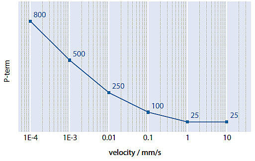
To obtain the smallest possible following errors regardless of velocity, a function adjusting the P-term to the current velocity can be implemented in all supported software environments, e.g. by using an empirical formula or a lookup table.
Author: Dr. Christian Benz is development engineer for piezomotor products at Physik Instrumente (PI) GmbH & Co. KG.
Blog Categories
- Aero-Space
- Air Bearing Stages, Components, Systems
- Astronomy
- Automation, Nano-Automation
- Beamline Instrumentation
- Bio-Medical
- Hexapods
- Imaging & Microscopy
- Laser Machining, Processing
- Linear Actuators
- Linear Motor, Positioning System
- Metrology
- Microscopy
- Motorized Precision Positioners
- Multi-Axis Motion
- Nanopositioning
- Photonics
- Piezo Actuators, Motors
- Piezo Mechanics
- Piezo Transducers / Sensors
- Precision Machining
- Semicon
- Software Tools
- UHV Positioning Stage
- Voice Coil Linear Actuator
- X-Ray Spectroscopy

