Counterbalancing, also known as weight force compensation, is essential in precision motion control — particularly for direct-drive vertical translation stages (Z-stages) used in nanopositioning applications. It serves to counteract the force of gravity, improving system stability, enhancing dynamic performance, reducing motor currents, and increasing operational safety.
A well-designed counterbalancing system offsets the weight of the moving stage and its payload, enabling smoother, more efficient motion across a wide range of applications. By leveraging various technologies, counterbalance solutions optimize performance while minimizing mechanical and electrical strain. This tech note explores the different counterbalancing mechanisms implemented by PI, highlighting their respective advantages and limitations.

Pneumatic and Magnetic Counterbalance Designs
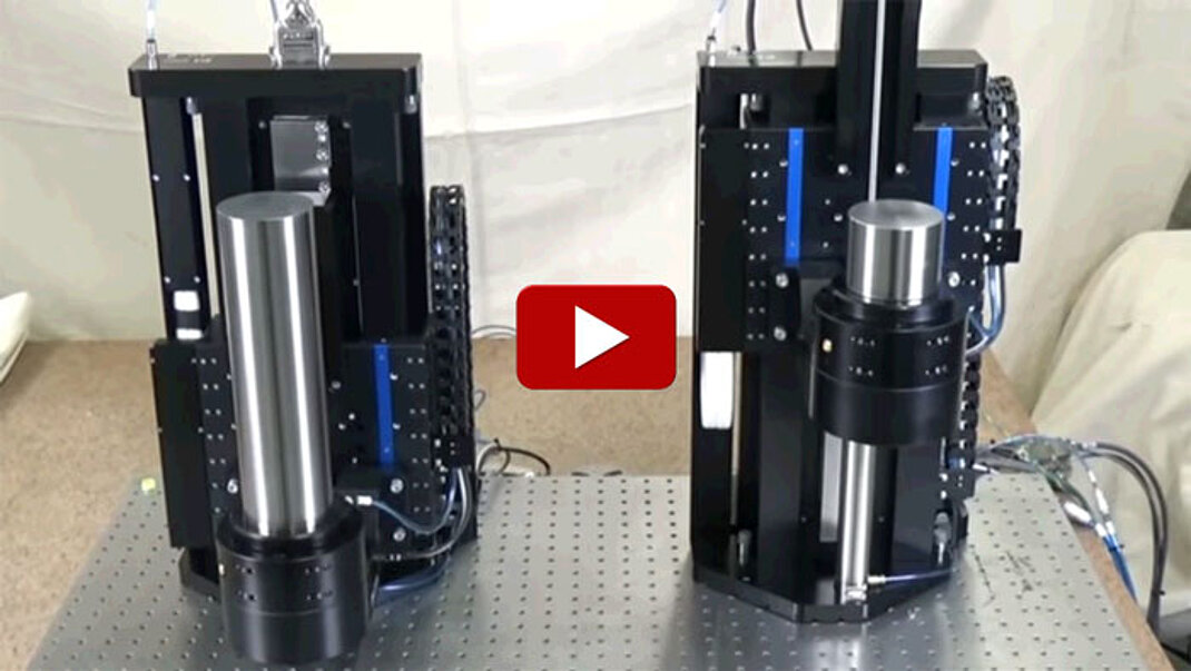
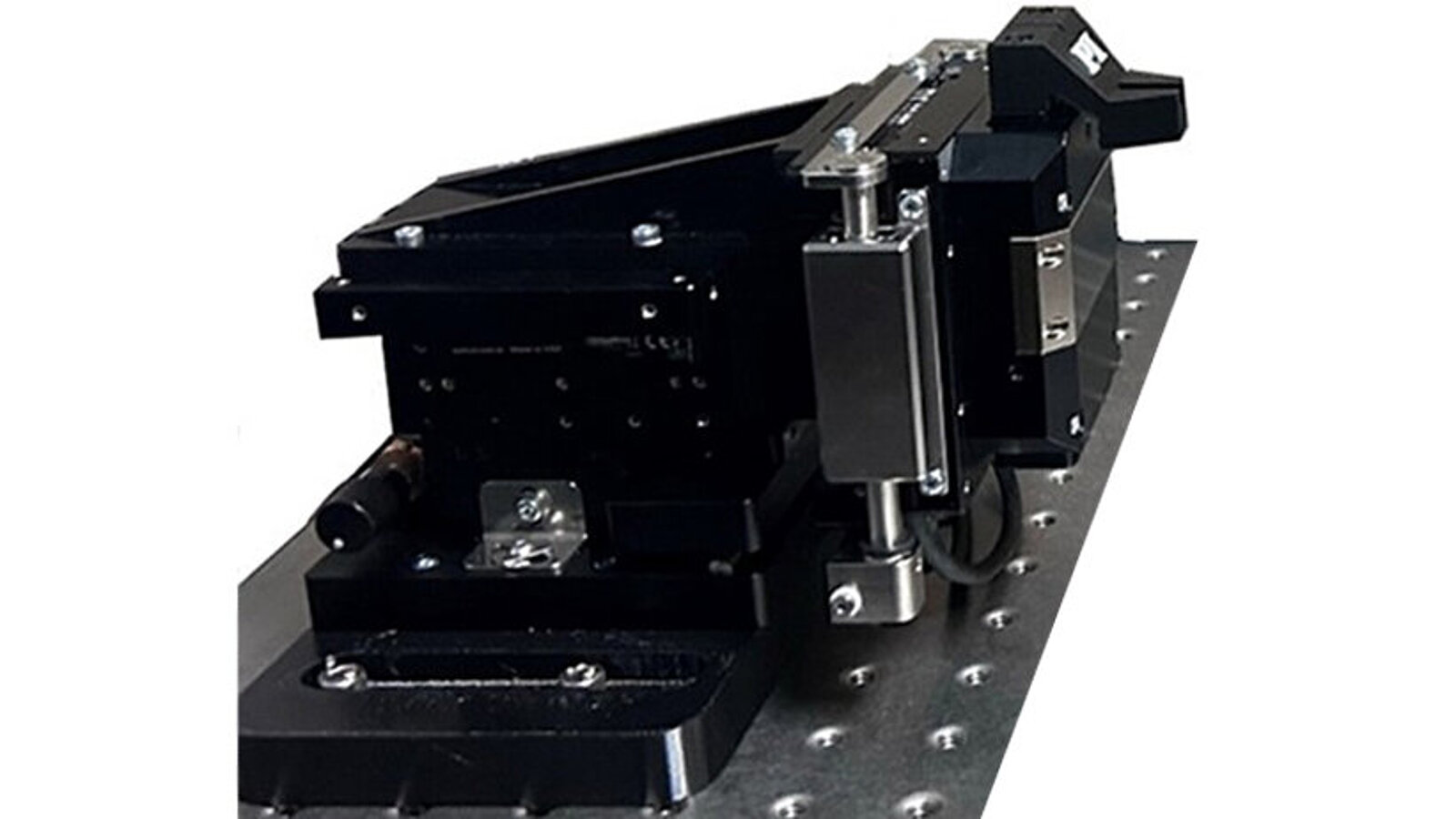
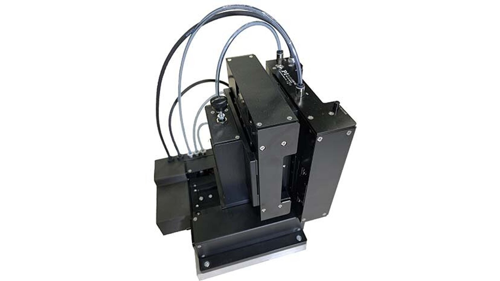
PI has investigated multiple counterbalance techniques for vertical translation stages and provides two standard solutions to meet application-specific needs: pneumatic and magnetic. The optimal solution depends on the performance requirements and stage design. To align with the characteristics of each platform, PI integrates pneumatic counterbalances into vertical air bearing Z-stages, while magnetic counterbalances are used with mechanical cross-roller bearing stages.
The table below compares these two approaches, illustrating why each was selected for its respective stage technology.
Pneumatic | Magnetic |
No travel/length limitation: up to 200mm readily available | Limit with travel/length and load capacity due to magnet size (up to ~50mm) |
Greater payload capacity | Payload capacity limited |
Emergency brake, in the event of loss of air to prevent the payload from potentially crashing: Settling time is ~500ms (loss of motion when braking) | No brake is needed |
Up to 100~150mm/sec speed limitation: Slower dynamics | No speed limitation: Higher/faster dynamics |
Ideal for air bearing stages because compressed air is already available | Pneumatic can be used for mechanical bearing stages with longer travel but would need compressed air |

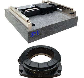
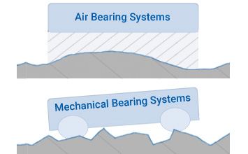
Mechanical Bearings vs Air Bearings
Mechanical cross roller bearing stages and air bearing stages often target distinct applications due to their differences in performance and cost. Following is data further illustrating the differences in performance.
| V-571.075B1MZ or V-572.075B1MZ | A-123.150B1ZB |
Pitch | 75 µrad | 20 µrad |
Yaw | 25 µrad | 20 µrad |
Straightness | 2 µm | 1 µm |
Flatness | 2 µm | 1 µm |
Velocity | 0.5 m/s | 0.5 m/s |
Acceleration | 10 m/s2 | 20 m/s2 |
Payload Capacity | 40 N (~ 4 kg) | 400 N (~40kg) |
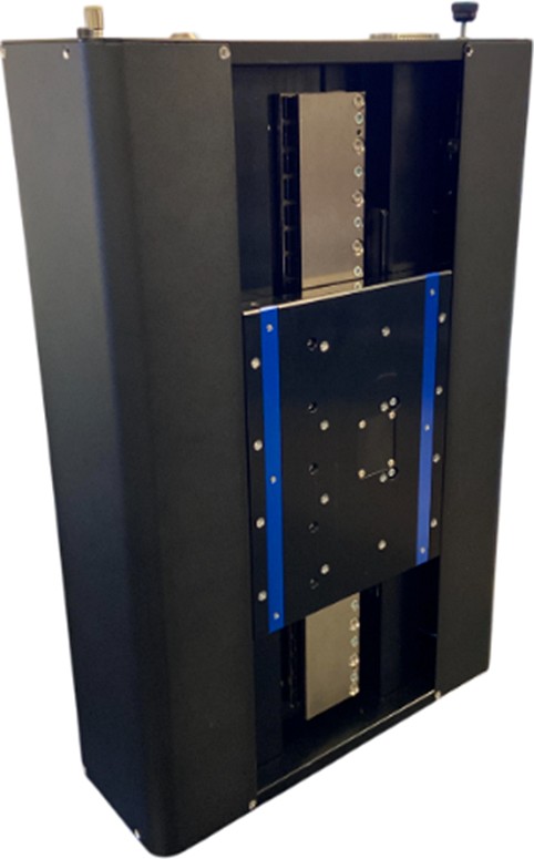
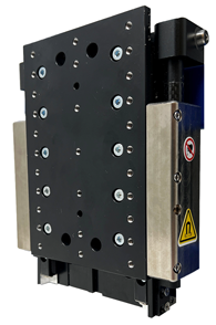
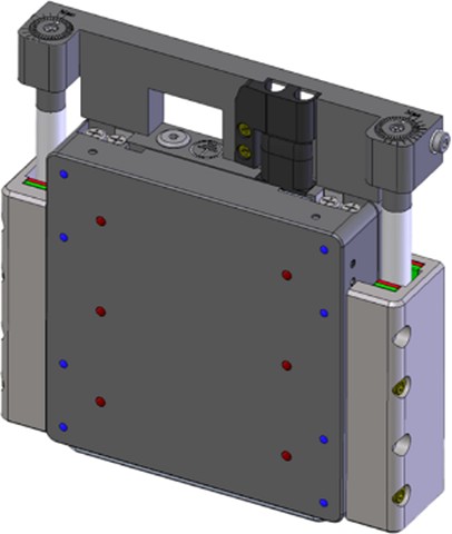
Translation Stages with Available Magnetic Counterbalance
- V-121 Miniature Voice-Coil Linear Stage
- V-141 Compact High-Precision Direct Drive Linear Stage, also used in the F-141 multi-axis photonics alignment system
- V-571 Ultra-Precision Direct Drive Linear Nanopositioning Stage
- V-572 Ultra-Precision Direct Drive Linear Nanopositioning Stage
- V-308 Direct-Drive Fast Focusing Stage

If you need support with selecting a counterbalanced stage, or a complete motion solution, that best fits your application, please contact our applications engineers.


Blog Categories
- Aero-Space
- Air Bearing Stages, Components, Systems
- Astronomy
- Automation, Nano-Automation
- Beamline Instrumentation
- Bio-Medical
- Hexapods
- Imaging & Microscopy
- Laser Machining, Processing
- Linear Actuators
- Linear Motor, Positioning System
- Metrology
- Microscopy
- Motorized Precision Positioners
- Multi-Axis Motion
- Nanopositioning
- Photonics
- Piezo Actuators, Motors
- Piezo Mechanics
- Piezo Transducers / Sensors
- Precision Machining
- Semicon
- Software Tools
- UHV Positioning Stage
- Voice Coil Linear Actuator
- X-Ray Spectroscopy