Case Study: Photonics Chip Level Test Strategies for Production Environments
Design Considerations for Maximizing Alignment System Performance Under Real-World Disturbances: Vibration, Thermomechanical Drift, and Structural Integrity
Integrated photonics is becoming essential to support the growing bandwidth and energy demands of large language models (LLMs) and hyperscale datacenters. As traditional electrical interconnects approach their performance limits, photonic integrated circuits (PICs) offer a scalable, low-power solution for high-speed optical communication. With PICs now being deployed in high-volume manufacturing, the demands on precision test automation systems have intensified.
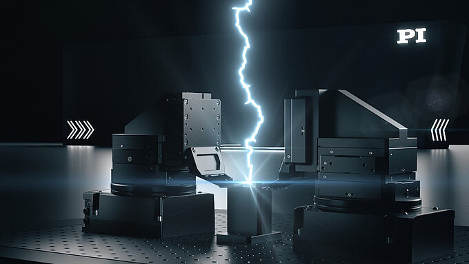
Achieving reliable, sub-micron alignment under production conditions — characterized by mechanical vibration and thermal variation — requires sophisticated system design and dynamic performance control. Precision alignment platforms, like the PINovAlign42, are critical to ensuring high-yield PIC production, directly enabling the scalability and efficiency of next-generation AI infrastructure.

This article explores key strategies for maintaining alignment accuracy under real-world conditions. It begins with an anatomy of photonics test automation design, followed by an in-depth look at production-scale photonics probe dynamics. We then examine the impact of both direct and indirect vibration disturbances and conclude with practical measurement techniques and mitigation strategies to ensure stable, high-performance photonic coupling on the factory floor.
The discussion examines the design of the 6DoF PINovAlign42 alignment system — engineered for PIC testing — and how it maintains nanometer-level precision under production-scale vibrations. We explore both direct and indirect dynamic effects, supported by real-world data and mitigation strategies that preserve speed and throughput.
Designing for Precision in Motion: Important Aspects for Robotics in Photonics Test Applications
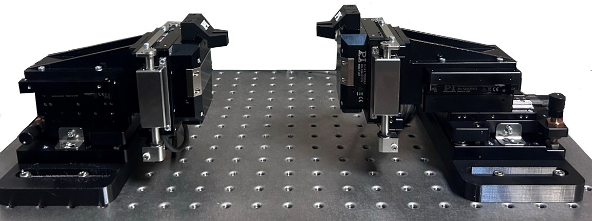
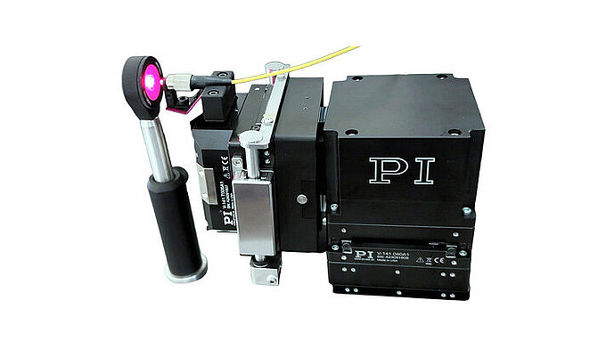
A successful photonics test system must combine nanometer-scale precision with high-speed dynamics in a compact, low-wear design. The PINovAlign42 achieves this within a 100mm cube, delivering 6DoF motion, an adjustable magnetic counterbalance for varying loads, and high responsiveness around the optical axis. Stability in pitch and yaw, along with built-in damping to suppress high-frequency resonances and prevent axis crosstalk, ensures reliable nanoscale alignment.
Key Requirements
- Compact (100mm x 100mm x 100mm) with minimum probe arm reach required
- 6-Degrees of freedom w/ minimal wear under high duty-cycle repetitive motions
- Short stroke in linear and angular travel (25mm/10deg)
- Supporting light applied loads (at <500g) w/ adjustable magnetic counterbalance
- High dynamics (especially in higher order terms – r’, r’’) to 2g, accelerations
- Optical axis roll is highly dynamic and responsive to 1,000deg/s^2
- Pitch/Yaw are highly stable, adjustable and lockable
- Minimal position adjustment and stability at ~ 30nm
- Inherent damping of high-frequency resonances w/ minimal crosstalk

Component Level Considerations-Linear Motor
One of the key components enabling the performance of the PINovAlign42 is its Halbach Array Linear Motor — the powerhouse of the system. Originally developed by Klaus Halbach at Lawrence Berkeley National Laboratory for use in particle accelerators, the Halbach array is designed to concentrate magnetic force on one side while nearly eliminating it on the opposite. This clever magnet arrangement generates a highly focused magnetic field, which significantly increases force density and motor efficiency.
For compact systems, like photonics aligners, this is a major advantage. The concentrated magnetic field provides more force in a smaller footprint, making the motor both powerful and space-efficient — ideal for precision tools operating in constrained environments. A B-field simulation from our finite element analysis visually confirms how the magnetic field lines are tightly corralled and intensified, highlighting the effectiveness of this configuration in delivering high dynamic performance within a compact design.

Component Level Considerations — Glass Scale Linear Encoder
An essential component of the PINovAlign system is the glass scale linear encoder, which serves as the primary feedback mechanism for position control. This encoder provides direct, high-resolution optical feedback by measuring the position of the stage at the point of load. In this configuration, the glass scale is affixed to the moving carriage, while the optical read head is integrated into the stationary base, enabling continuous, real-time monitoring of displacement.
The encoder operates with a 20µm signal period using a SIN/COS analog output at 1V peak-to-peak. When coupled with 14-bit interpolation within the drive electronics, the system achieves a position resolution of approximately 1 nanometer. This level of precision is critical for maintaining alignment stability in photonics applications where sub-micrometer tolerances are required and underscores the importance of direct metrology at the load for minimizing structural deflection and measurement uncertainty.

Component Level Considerations — Body and Bearings
The smooth, precise motion of the PINovAlign system is largely attributable to its optimized body and bearing design. The structural frame is constructed from aerospace-grade anodized aluminum alloy (6061-T6), chosen for its exceptional strength-to-weight ratio, high fatigue resistance, and ability to maintain rigidity with minimal moving mass. These characteristics are essential for applications requiring the delicate handling of photonics components, such as fiber array units (FAUs), lensed fibers, and precision fixtures.
Motion guidance is provided by high-rigidity, precision-machined crossed roller bearings made from high-carbon steel. These bearings are preloaded and feature anti-creep and low-friction properties, ensuring smooth, repeatable motion over the short travel ranges typical in photonic alignment tasks. Designed for durability, they maintain consistent performance even under the demanding conditions of high-throughput production environments. The combination of a stiff, lightweight structural body and robust bearing technology enables the system to achieve the nanometer-level stability and repeatability required for advanced photonics testing.

Evaluating and Understanding Photonic Probe Dynamics Performance
To accelerate signal acquisition during photonic alignment, the PINovAlign42 system employs algorithmic first light search and signal optimization routines that are driven by high-dynamic, periodic motion. The dynamic performance of these routines is evaluated based on the system's ability to maintain precision across various operating frequencies. In practice, this requires balancing injected motion dynamics with the resulting disturbances, positional stability, and error behavior — along with careful attention to the pathing characteristics of the search algorithm.


Transfer Function Characterization
Evaluating Resonance Signatures of Precision Robotic Alignment Systems
Each mechanical system exhibits an inherent frequency response that is shaped by its intrinsic mechanical design, engineering choices, and the surrounding operating environment, including the control module. This frequency response function can be characterized through the selective application of ascending frequency current excitation sweeps, although alternative methods such as white noise excitation may also be employed.
By analyzing the gain and phase relationship between the excitation signal and the system’s response — commonly referred to as the open-loop transfer function — engineers can identify critical features, such as first-mode resonances as well as gain and phase margins that directly influence system stability. In the absence of such analysis, the servo responsiveness and gain settings must be carefully tuned to avoid instability. This typically involves maintaining sufficient safety margins, such as a gain margin of 6dB and a phase margin of 30 degrees, to accommodate variations in design and environmental conditions.

Indirect Vibration Disturbance Injection
Environmental Vibrations Unrelated to Direct Robotic Aligning Action
Photonic probe and test production tools are composed of both structural and peripheral components that must be engineered to support robotic photonic alignment systems while carefully balancing multiple constraints. These include cost considerations, strict size and volumetric limitations, and the need to integrate additional sensors, instrumentation, and electrical probes. The system must also accommodate physical contact or inertial influences from wafer or chip handlers and fixtures.

Environmental regulation is another critical factor. These tools must effectively manage forced heating and cooling through the integration of vacuum pumps, compressors, fans, heaters, chillers, and similar components. The choice of materials — such as aluminum probe arms and base plates, steel welded frames, and suspended structures made from granite or aluminum — also plays a key role in determining overall system rigidity and thermal stability.
At the same time, the equipment must be designed to allow seamless interaction with both robotic machine handlers and human operators, whether as part of a dedicated photonics test system or as a hybrid tool performing additional assembly or process functions. Importantly, the system must deliver robotic alignment precision that supports stable optical coupling at sub-100-nanometer tolerances, even in the presence of both direct and indirect disturbances. This demands a platform that is not only highly dynamic but also exceptionally stable.
Case Study: Insertion Loss under Forced Cooling Disturbance

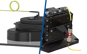
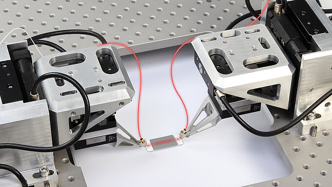
To assess the effects of localized forced cooling on photonic alignment performance, a profiling experiment was conducted using a characterization algorithm with fiber array-to-fiber array coupling through a four-channel fiber array unit (FAU) featuring a 50µm core and 250µm channel spacing in a loopback configuration.
In this setup, a 1Hz X-scan algorithmic signal search was used to locate the peak optical coupling position, after which the system held that position stable for four seconds without active tracking. The results shown below compare two operating conditions: with the cooling fan turned off (red trace) and with the fan turned on (yellow trace). The data clearly demonstrate that the presence of localized forced airflow and structurally coupled vibration source introduces measurable disturbances, negatively affecting coupling stability and increasing insertion loss.
Structurally Coupled Fan Assembly Impact on Setup

To minimize the impact of forced cooling on fiber array photonic edge coupling, elastomer interfaces were introduced at the structural coupling point between the fan and the robotic aligner. This approach was tested using a four-channel, multimode fiber array under three different conditions.
In the first case, an X-scan area signal search was performed at 20Hz with no fan present, serving as the baseline condition (red trace). In the second case, the same scan was conducted with the fan directly coupled to the robotic aligner structure (yellow trace), introducing mechanical vibrations that degraded coupling. In the third case, the fan remained in place but was mounted using elastomeric dampers at the structural interface (blue trace), which helped isolate the robotic platform from vibration-induced disturbances.
The results revealed clear differences in normalized insertion loss and coupling stability across the three scenarios. The use of elastomeric interfaces significantly reduced the negative effects of forced cooling, improving optical coupling performance compared to the setup with direct structural coupling.
Quantitative results from the experiment further illustrate the impact of structural vibration on photonic coupling performance. When no fan was present, the system achieved optimal alignment stability, serving as the reference baseline. With the fan directly coupled to the robotic aligner, the mean insertion loss increased to 0.79dB, indicating a significant degradation in coupling efficiency due to mechanically transmitted disturbances. However, when elastomeric interfaces were introduced at the fan’s structural coupling point, the mean insertion loss improved to 0.49dB. This demonstrated that vibration isolation through elastomer damping can substantially mitigate the adverse effects of forced cooling, restoring much of the coupling stability and preserving photonic alignment performance.
Summary: Designing for Dynamics and Precision in PIC Test Systems
In summary, frequency sweep and transfer function characterization are essential tools for identifying first-mode resonances in robotic photonics aligners and improving performance. These insights can improve both the mechanical design and help with the strategic application of notch filters and servo gain adjustments to ensure optimal system stability. Successful deployment of algorithmic alignment routines requires a thorough understanding of the resonances introduced by the robot itself to avoid unintentionally exciting structural harmonics. This demands a combination of time- and frequency-domain analyses, such as Fast Fourier Transform (FFT), to accurately diagnose and mitigate dynamic disturbances.
Dynamic motion profiles must be carefully tuned to match the specific application and environmental conditions, ensuring high performance without compromising stability. In particular, active cooling systems — often necessary for thermal regulation — should not be rigidly coupled to the alignment platform, as they can introduce indirect vibration disturbances that degrade coupling performance. Experimental results clearly demonstrate that such forced cooling can negatively impact key coupling metrics. However, these effects can be substantially reduced through the use of elastomeric damping materials at structural interfaces, offering a practical and effective strategy for improving photonic alignment reliability in production environments.


Blog Categories
- Aero-Space
- Air Bearing Stages, Components, Systems
- Astronomy
- Automation, Nano-Automation
- Beamline Instrumentation
- Bio-Medical
- Hexapods
- Imaging & Microscopy
- Laser Machining, Processing
- Linear Actuators
- Linear Motor, Positioning System
- Metrology
- Microscopy
- Motorized Precision Positioners
- Multi-Axis Motion
- Nanopositioning
- Photonics
- Piezo Actuators, Motors
- Piezo Mechanics
- Piezo Transducers / Sensors
- Precision Machining
- Semicon
- Software Tools
- UHV Positioning Stage
- Voice Coil Linear Actuator
- X-Ray Spectroscopy