Defining Micropositioning and Nanopositioning Terminology
Understanding Key Terms for Performance and Precision in Micro- and Nanopositioning Systems

The terminology used to specify and describe the performance of precision motion control equipment is often subject to significant misinterpretation in everyday usage. Unfortunately, terms frequently employed by both users and manufacturers of micropositioning hardware carry different meanings for different individuals. To avoid a crane vs. crane scenario (see image), it’s essential that we establish a common understanding when discussing terms like repeatability, accuracy, precision, and related concepts in micropositioning and nanopositioning applications.
To help clarify, the accompanying glossary defines the most common terms. However, a few of these terms require more detailed explanation beyond their brief definitions.
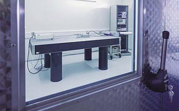
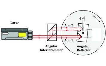
One of the most misunderstood — and yet most crucial — terms is accuracy, or absolute accuracy. This term is often confused with others, such as precision, resolution, repeatability, or sensitivity. In simple terms, accuracy is the maximum expected deviation between the actual position and the target (or ideal) position for a given input. To measure accuracy in micropositioning or nanopositioning equipment, an external laser interferometer is the best tool for the job. Some laser interferometers can measure both linear and angular positions with very high accuracy. An autocollimator is another optical tool for precise angular (error) measurements.
The consequences of misunderstanding these terms can be significant. For example, if a user mistakes resolution for accuracy, they may encounter issues in achieving their desired outcomes. As a rule of thumb, to reach a particular level of accuracy, the resolution typically needs to be an order of magnitude finer, but that’s not a guarantee. High resolution can exist without high accuracy, for example when the position measuring device has periodic errors or is mounted not perfectly in parallel with the motion path.
Another common point of confusion arises from misinterpreting specifications on a spec sheet with achievable performance in practical use cases. Typically, specifications are given for "ideal" conditions, such as an ambient temperature of 20°C, normal atmospheric pressure, unidirectional movement at a specific speed, and minimal load. Unfortunately, these ideal conditions are rarely, if ever, met in real-world applications. It’s essential for the user to confirm with the manufacturer the exact conditions under which the advertised performance figures apply and to understand how those figures may change under the actual conditions of the intended application.
Micropositioning / Nanopositioning Glossary
- Absolute Positioning Command: A positioning command where all moves are referred to as a system’s zero. For instance, a command to move by 1 in a linear positioning system will bring the object to the point x = 1, regardless of where the object was located prior to the command.
- Accuracy: The maximum expected difference between the actual and the ideal (desired) position for a given input.
- Alignment system: A setup of tools and technologies designed to precisely position and orient components or objects relative to each other, ensuring accurate alignment in applications like optics, photonics, robotics and manufacturing.
- Autocollimator: An optical instrument used to measure small angular displacements with high precision by reflecting light off a mirror and detecting deviations from the initial alignment.
- Backlash: The portion of an input that produces no output after reversing direction; can be a result of poor meshing between drive train components (i.e., gear teeth in a gear-coupled drive train) or insufficient axial preloads.
- Basic Bearing Life: Minimum calculated bearing life under rated load.
- Bidirectional Repeatability: The ability to return to a position from random directions; see Repeatability.
- Concentricity: The variation between a rotating member's actual centerline and the actual axis of rotation of the stage.
- Creep: A slow, time-dependent, and unintended movement or position drift, typically caused by internal material deformation, tension, thermal expansion or lubricant films.
- Cross-coupling: In multi-axis devices, a positional change in one axis as a result of an input to the other axis — for instance, a change in the tilt of a mirror in response to a linear displacement.
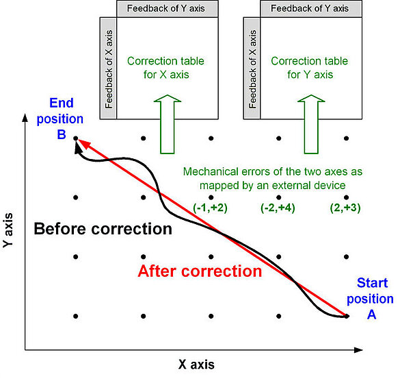
- Dynamic Error Compensation: See Error Mapping. With dynamic error compensation errors are corrected on the fly, not just at the end of each move.
- Error Mapping: The process of identifying, recording, and compensating for systematic errors in a motion system to improve positioning accuracy by creating a correction profile that is uploaded to the motion controller. External precision instruments such as laser interferometers, are usually employed for error mapping.
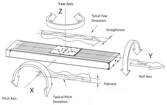
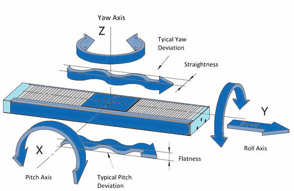
- Flatness: The measure of how close all points of a given plane surface are to the theoretical plane of that surface. Often used with mirrors or optics.
- Flatness Of Travel: The ability of a system to keep all its points in their respective horizontal planes during movement.
- Hysteresis: A difference in the absolute position of an object after traveling in one direction and then reversing to return by the opposite way. It is due to elastic forces accumulated in various drive train components (a leadscrew windup, couplings, bearings, etc.). Often confused with Backlash.
- Incremental Move Command: A motion command refers to the current position of the controlled object. Thus, if an object is at x = 10 and a command is given to move by +5, the object will move to x = 15 (not to x = 5 as it would in an absolute system).
- Input Shaping:An advanced technique used to modify the input command of a motion system to reduce or eliminate vibrations by applying a series of pre-calculated impulses that counteract oscillations.
- Lead: The distance traveled for each rotation of a leadscrew.
- Leadscrew Pitch: In the Imperial / English system, the number of revolutions required to move an object mounted on a leadscrew by one inch. In metric systems, the peak-to-peak distance between the threads of a screw; see Lead.
- Learning Based Motion Control:An approach that uses machine learning algorithms to improve a system's ability to perform precise and adaptive movements by learning from past experiences and real-time feedback.
- Minimum Incremental Motion: The minimum controllable motion interval that the system is capable of producing repeatably.
- Orthogonality: A measure of how accurately a system’s axes maintain a 90° relationship among them.
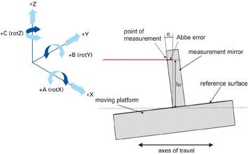
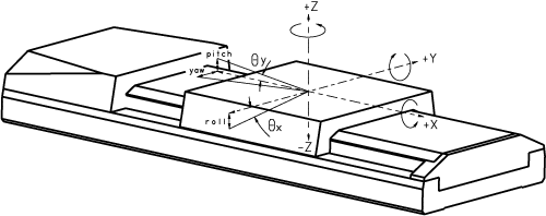
- Pitch (Tilt): In a linear stage, an unwanted tendency of a positioned object to move "up and down" (tilt) during a pure horizontal translation.
- Precision: Sometimes used synonymously to accuracy and (falsely) to repeatability. The average deviation from the ideal position for a given input.
- Repeatability: The ability of a system to bring an object to a desired position repeatedly (see Bi-directional Repeatability and Precision). Depending on what norm is used to measure it, it can be the worst result from several tests or provided as standard deviation (1, 2, 3,… sigma).
- Resolution: Often confused with Minimum Incremental Motion. In a closed loop system, the sensor resolution. In a geared drivetrain, it is often used to specify the calculated, theoretical size of one step (based on the number of microsteps or rotary encoder counts, gear reduction ratio, and drive screw pitch).
- Rigidity: The ability of a servo motor or system to resist external force or torque interference.
- Roll: In a linear stage, an unwanted tendency of a positioned object to rotate about the axis of its translatory motion.
- Runout: In a linear stage, any unwanted motion other than pure translation. Thus, runout may include yaw, pitch, and roll.
- Sensitivity: The minimum input capable of producing an output motion.
- Stability: The ability of a system to maintain positioning accuracies with passage of time in a given ambient. It is a function of wear and tear, lubricants (film thickness may contribute to error), and temperature.
- Straightness: The ability of a system to move an object along a perfectly straight path. Air bearings can provide the best straightness and flatness.
- Translation stage: A precision mechanical device that allows controlled linear movement of an object along one or more axes, commonly used in applications requiring precise positioning and alignment.
- Wind-up (Torsional): An effect whereby a torque applied to the drive end of a leadscrew rotates that end farther than the output end.
- Yaw: In a linear system, an unwanted tendency of a positioned object to move left and right from the motion axis.
- Zero-Backlash Gearbox: A type of gearbox designed to eliminate play, or lost motion, between input and output shafts, allowing for precise, smooth, and highly accurate transmission of torque without delays or positional errors.
Multi-Axis Motion Control – Additional Complexity
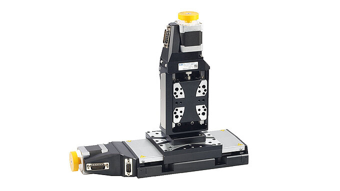
Most of the terms of the above glossary apply primarily to single-axis positioning. However, many applications require multi-axis operation, where additional factors come into play. Some of the most critical terms and concepts for multi-axis positioning are summarized below. Cross-coupling, as previously defined, is especially important in multi-axis systems.
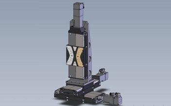
The cantilever effect is one of the most significant challenges in multi-axis positioning. This effect arises when a load, specifically its center of gravity, is positioned off-axis. In multi-axis positioners, the center of gravity of each positioner often lies off the axis of another stage, which can lead to flexing or bending and potentially increase backlash. To minimize the cantilever effect, the lowest positioner should have the widest base (distance between bearings). For the best performance, true planar stages (available with air bearings) where both the X and Y axis use the same base, are recommended
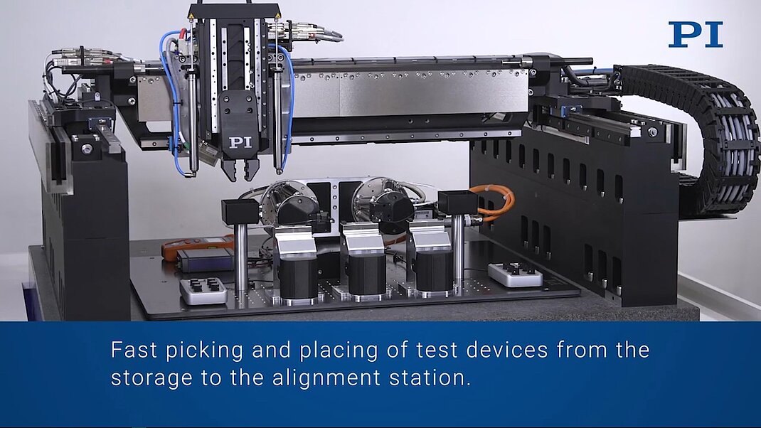
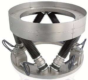
Inertia is another critical consideration in multi-axis systems. The lowest stage in a multi-axis setup supports all upper stages, as well as the sample, meaning each stage “sees” the inertia of the entire system above it. This impacts the system's ability to accelerate and decelerate the sample while maintaining the desired level of accuracy. Parallel kinematics can significantly reduce the inertia. In hexapod 6-axis positioners for example, there is only one common platform supported by 6 actuators that all share the same inertia.
Global accuracy defines the accuracy in a multi-axis positioning system and could best be described as a sphere of confusion. It takes into account the cumulative errors (both on axis and geometric) from each individual axis, resulting in a three-dimensional tolerance range that represents the maximum deviation between the commanded and actual position within the entire system. Global accuracy is not confined to a single plane but exists within a three-dimensional space, such as a sphere or cube.
Thermal materials matching becomes increasingly important in multi-axis systems. For optimal performance, materials with closely matched thermal-expansion coefficients should be chosen to minimize distortion due to temperature changes. Bolting an Invar stage on an aluminum base can yield worse overall precision than starting with a lower-cost aluminum stage in the first place.
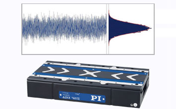
Finally, natural frequency is a critical parameter, to eliminate or reduce parasitic mechanical oscillations. The greater the resonant frequency of a system, the faster it can react to external disturbances and system inputs. Modern control algorithms, such as InputShaping, and learning control can help improve performance.
Precision Motion Recipe for Success: Close Contact between User and Supplier
Users of micropositioning and nanopositioning equipment should establish close contact with the engineers of the equipment’s manufacturer to ensure a clear, mutual understanding of the application's specific requirements and the capabilities of the available systems. By collaborating directly with the engineers, users can communicate critical details about performance expectations, environmental conditions, and any unique challenges that may impact equipment performance, such as temperature fluctuations or load dynamics. This open line of communication allows manufacturers to provide insights into how their systems can be optimized or customized to meet these demands, potentially recommending specialized configurations, additional features, custom tuning, or even modifications to enhance performance and accuracy. Such a partnership not only helps to align the equipment’s capabilities with the application’s needs but also minimizes the risk of misinterpretation or unmet expectations, ultimately leading to more reliable, precise, and effective solutions.
If you need support selecting the right micropositioning or nanopositioning system for your next project contact a member of the PI team directly.
Blog Categories
- Aero-Space
- Air Bearing Stages, Components, Systems
- Astronomy
- Automation, Nano-Automation
- Beamline Instrumentation
- Bio-Medical
- Hexapods
- Imaging & Microscopy
- Laser Machining, Processing
- Linear Actuators
- Linear Motor, Positioning System
- Metrology
- Microscopy
- Motorized Precision Positioners
- Multi-Axis Motion
- Nanopositioning
- Photonics
- Piezo Actuators, Motors
- Piezo Mechanics
- Piezo Transducers / Sensors
- Precision Machining
- Semicon
- Software Tools
- UHV Positioning Stage
- Voice Coil Linear Actuator
- X-Ray Spectroscopy

