XY-Linear Motion – The Difference between Planar XY-Stages, Integrated XY-Stages, and Stacked Stages
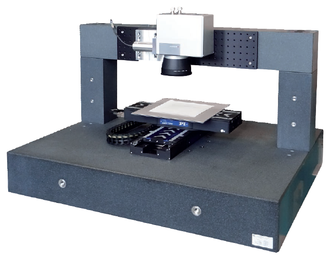
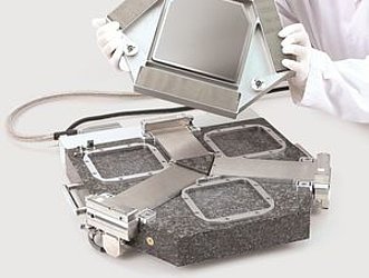
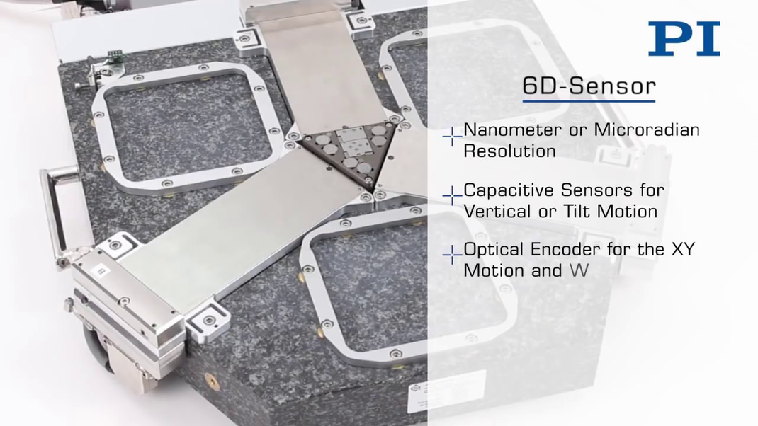
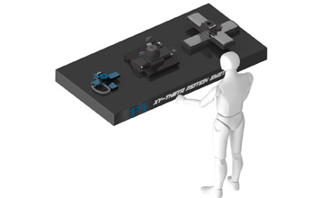
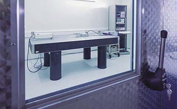
Left: A precision ground granite surface not only works well as the foundation for metrology equipment, but also provides an excellent basis for high performance XY tables, such as those used in laser processing (Image: PI). Right: A smooth, planar surface can be as critical for figure skating as for precision motion control (Image: Wikipedia)
In industries such as precision optics, semiconductor test/manufacture, laser processing, flat panel display manufacturing, etc., precision motion in multiple degrees of freedom is often required. When large surfaces need to be processed, the flatness specification (vertical deviations) of the positioning stages involved is especially critical, for example to reduce out of focus errors.
True Planar Motion - What is a Planar XY Stage?
The differences between stacked, integrated, and planar stage designs are often misunderstood by users. Planar XY-stages or XY-tables by definition use a common reference plane for both X and Y axis motion. True planar motion is not available with cross roller bearings – these are used in stacked, integrated designs.
Stacked, Integrated, and Planar XY Stages
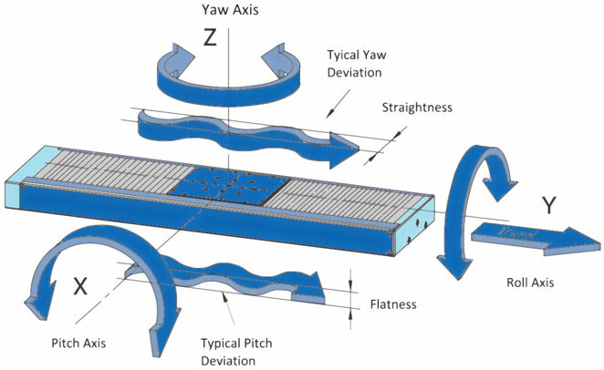
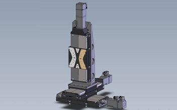
XY motion can be achieved by stacking two linear stages of similar stroke or type (depending on the application requirements, they can also be different). This modular design provides flexibility. The downside is – for long travel ranges – flatness errors and pitch/roll errors increase towards the end of travel, caused by the lack of support for the base of the upper axis.

Stacked multi-axis stage. X and Y flatness measurement shows the effect of the cantilevered, loaded Y axis on flatness. The lower X axis is not affected by the cantilever effect and shows significantly better flatness. More information on the performance of custom tuned 3-axis stages
Gantry XY Stages (Cartesian Robotic Stages)
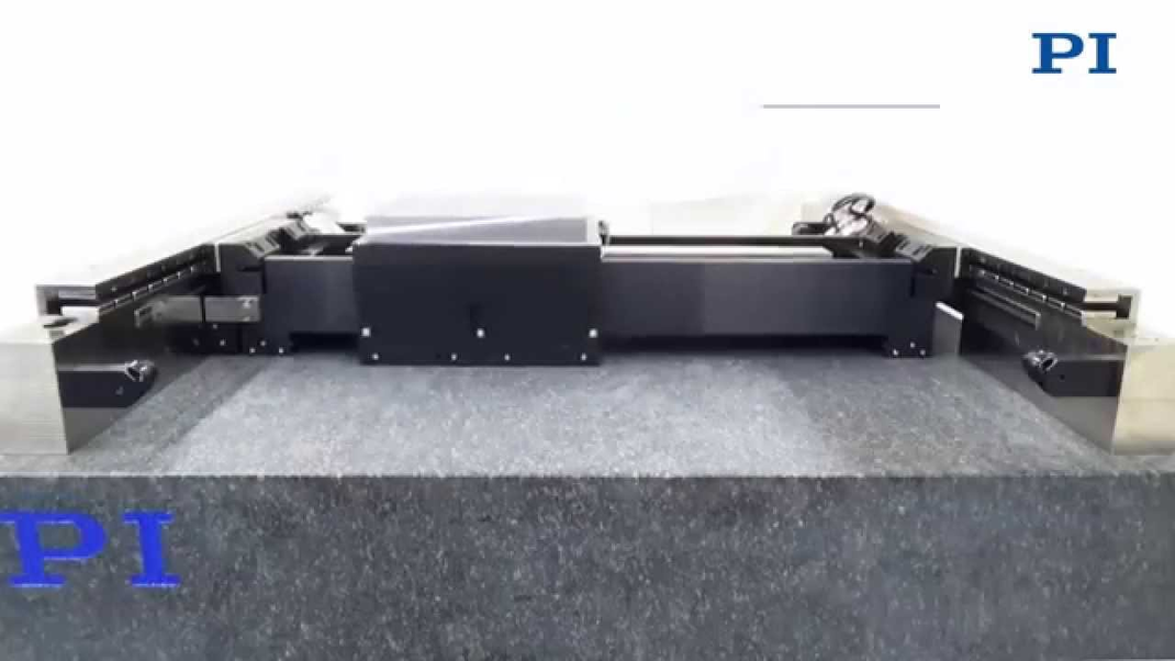
A Gantry-style XY stage is yet another form of stacked stage design. Gantry XY motion systems are often used when longer XY travel distances with heavy loads need to be covered, or when a stationary workpiece needs to be scanned or processed from above.
A motion controller with a special gantry control algorithm is required for maximum performance and to avoid binding.
Gantry XY motion systems come in a large variety, are often built on a granite base for extra high stability and accuracy and are often used in laser processing, imaging, and metrology applications.

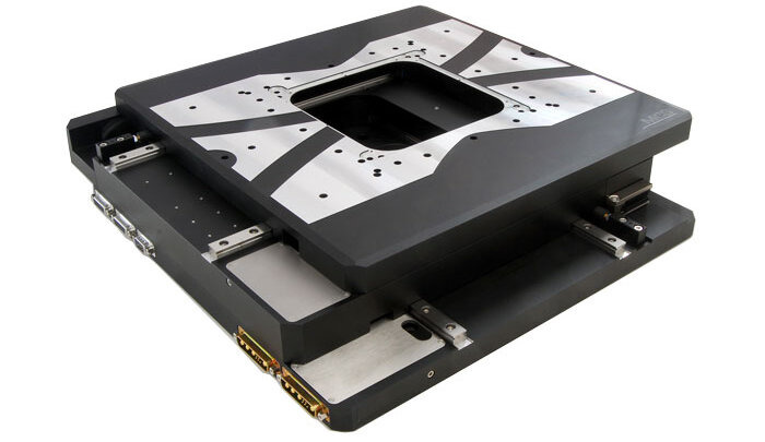
Integrated XY stages (often wrongly called planar XY stages) can be manufactured with a lower profile, because the central plate serves both as the moving top plate of the lower axis and bottom plate of the upper axes. Integrated XY stages typically have a square footprint and the wider base for the bearings reduces the above-mentioned geometric errors caused by the cantilever effect. Like stacked linear stages, they do remain within their own neutral position footprint.
The same type of bearings (crossed roller bearings, recirculating ball bearings, etc.) and drive mechanisms (lead screws, ball screws, linear motors) are available as with stacked linear stages.
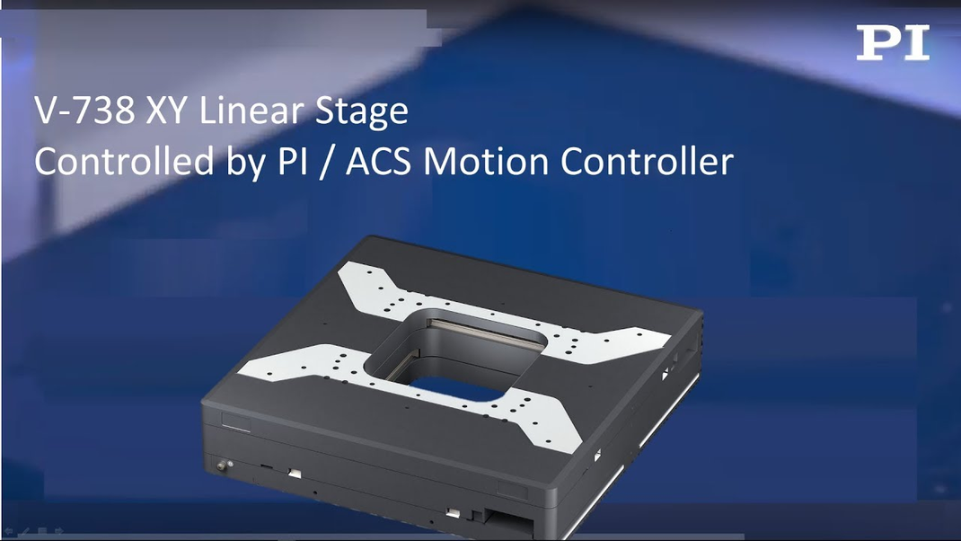
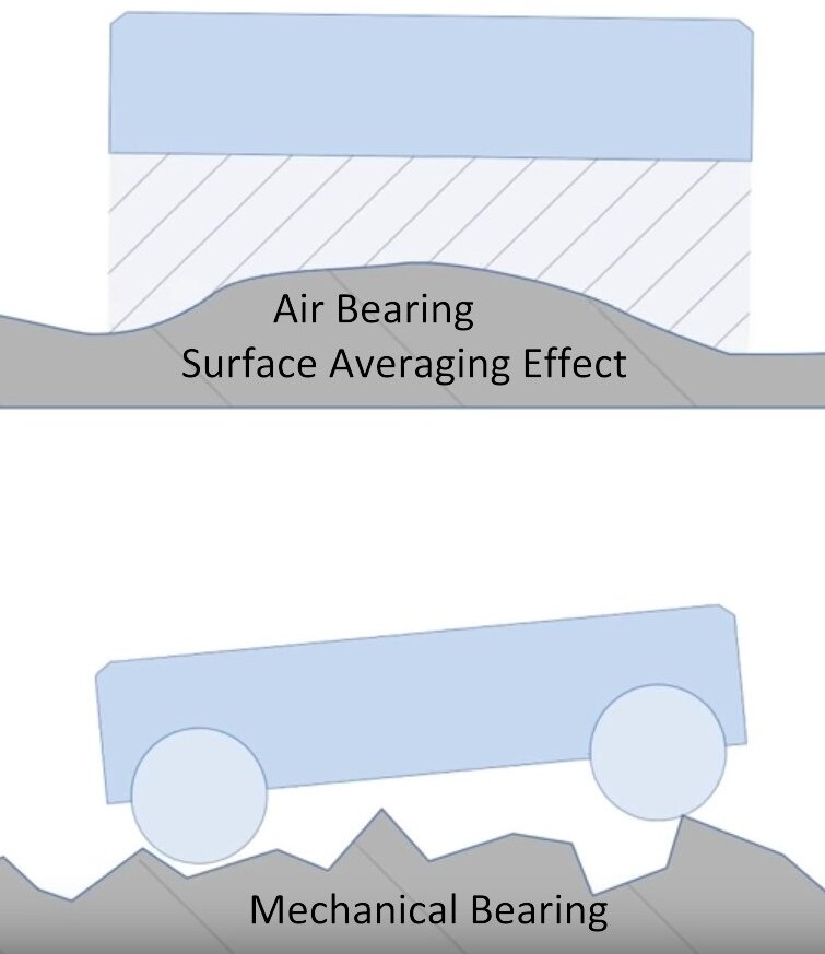
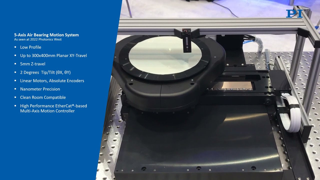
If motion outside the XY table footprint is not acceptable and / or the highest geometric performance is required, planar XY stages are available. Planar XY stages are usually based on air bearings, magnetic levitation or – very popular for short travel ranges – flexure guides.


Planar XY tables provide the highest geometric performance and are best suited for applications that require extremely high accuracy, such as often found in semiconductor wafer inspection.
Geometric Motion and Positioning Performance – Straightness and Flatness
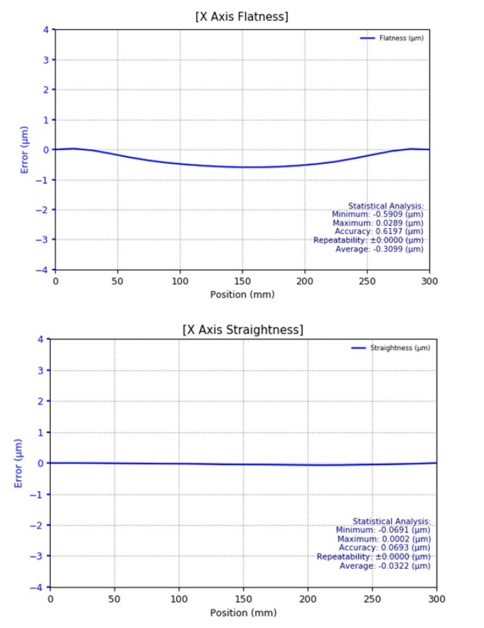
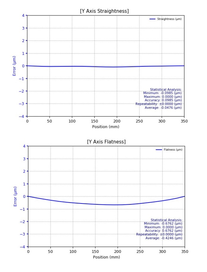
The following graphs show the excellent geometric performance in terms of straightness and flatness, where the planar air bearing stage concept excels over other XY-stage concepts.
As the above graphs show, air bearing planar 2-axis stages can achieve flatness of 1µm and better over hundreds of mm of travel. Putting this in perspective with the size of a typical ice-skating rink, we’re talking about deviations on the order of a few hair widths — across the whole area. While this might be the dream of many an athlete, a resurfacing machine with such performance is not available.
Footprint – Static vs. Variable
Another difference between a true planar XY stage and other 2-axis linear stage designs is evident in the footprint. While 2-axis planar stages are designed to keep the moving platform always inside the area covered by the base plate, this is not possible with stacked designs. They might appear to require less production space at first glance, but their travel range has to be added to the footprint, which may not be obvious from the drawings, when the stage is shown in its centered position.

Planar Flexure Nanopositioning Stages
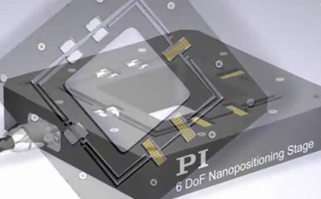
For short travel ranges, planar flexure guided stages are another option. Depending on the application, out of plane motion of only a few nanometers is tolerable. Semiconductor and AFM related tools require this outstanding performance. More information on piezo nanopositioning stages
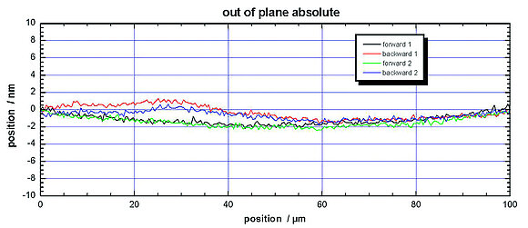
Planar Magnetic Levitation Stages (MagLev)
Magnetic levitation is yet another way to achieve true planar motion. The moving platform is not restricted by any mechanical restraints, just by magnetic fields. Depending on the complexity of the coils, drive circuitry, and sensors used, motion with up to 6 degrees of freedom can be achieved, with excellent geometric performance.
Blog Categories
- Aero-Space
- Air Bearing Stages, Components, Systems
- Astronomy
- Automation, Nano-Automation
- Beamline Instrumentation
- Bio-Medical
- Hexapods
- Imaging & Microscopy
- Laser Machining, Processing
- Linear Actuators
- Linear Motor, Positioning System
- Metrology
- Microscopy
- Motorized Precision Positioners
- Multi-Axis Motion
- Nanopositioning
- Photonics
- Piezo Actuators, Motors
- Piezo Mechanics
- Piezo Transducers / Sensors
- Precision Machining
- Semicon
- Software Tools
- UHV Positioning Stage
- Voice Coil Linear Actuator
- X-Ray Spectroscopy
