Self-Locking Actuator for Hexapod Applications Combines High Push-Pull Force with Picometer Resolution for Active Optical Alignment in Astronomy
1. Introduction
Astronomical telescopes usually employ active position control for primary mirror surfaces using motorized mechanical actuators. The motion needed is generally quasistatic, to compensate gravitational and thermal effects. Another application for precision actuators within the telescope at a significantly faster motion response is the high speed tip/tilt control of a secondary or tertiary mirror.
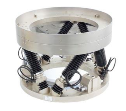
Fig 1.1 shows a typical 6-axis hexapod positioner designed for secondary mirrors. It performs micron level positioning using high precision motorized components, and some designs have integrated piezoelectric actuators for rapid tip -tilt movements of the secondary mirror.
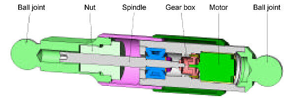
The classical design for a motorized actuator consists of a DC motor with an encoder, gears, and a leadscrew nut assembly to convert the rotary motion to linear translation. The achievable performance depends, for the most part, on the choice of mechanical components and the control algorithms. The physical size and mass of the actuation system is load dependent and for primary mirror applications often include counterbalancing mechanisms for offloading the motion drives. With high precision gears and leadscrews (e.g., Harmonic Drive gearheads, zero backlash ball, and roller screws) position resolutions of 0.1 to 0.5 µm can be achieved. The resolution can be bettered by adding a piggy-back piezo actuator with a high-resolution linear encoder, or by using motion deamplification techniques at the expense of added complexity and part count. All applications mentioned above require minimal energy consumption during operation for thermal control. An essential requirement then is that the units be self-locking when not under power, something which has required the addition of a brake acting on the leadscrew or motor for classical mechanical actuators. However, friction, play, and the associated manufacturing tolerances of the mechanical components limit the achievable position resolution in motorized actuator technology.
2. The Development of NEXLINE® Technology
Piezoelectric ceramic actuators however, acting as solid-state analog positioning elements, are not subject to these limitations. Piezo actuators can achieve extreme reliability and lifetime. An example is the NASA/JPL test of the PICMA® multilayer actuators form the Mars Mission. Here actuators were submitted to 100 billion cycles of life testing and survived without failures. For more information: Piezoelectric multilayer actuator life test and Precision Motion and Positioning Equipment on Mars Rover Curiosity – Still Going Strong.
The resolution of a piezo actuator is limited only by the noise on the control signal and is typically in the nanometer or picometer range. However, the displacement available with the piezo effect is limited to 0.1%-0.2% of the length of the piezo ceramics block. The implementation of piezo actuation to longer displacement (many millimeters) with high force has been very problematic over the years with vibrational/acoustic noise, low force, and low reliability from high wear rates as major technological hurdles. The motivation behind the development of NEXLINE® drives therefore was to provide the advantages of piezo actuators over long travel ranges while overcoming the technological hurdles mentioned above in a compact modular actuator.
2.1 Dither Mode Operation
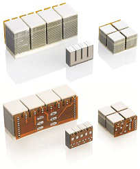
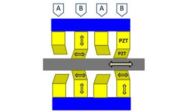
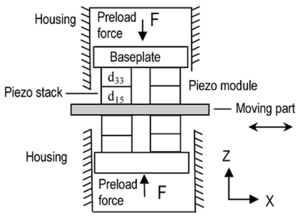
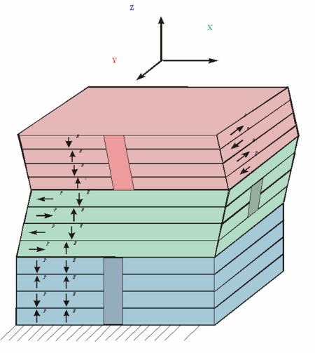
A NEXLINE piezoelectric step drive consists of an arrangement of piezoelectric elements polarized in different directions. Shear piezo elements, highly preloaded against the runner, drive it perpendicular to the interface in a direction which depends on whether their control voltage is rising or falling. See Fig 2.2 and 2.2a.
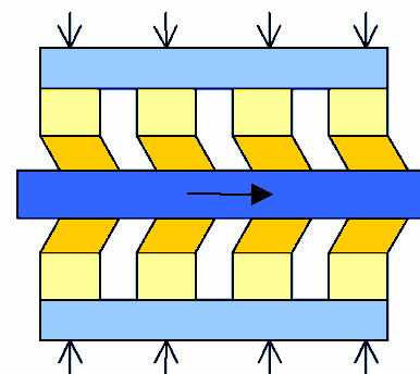
In dither operating mode, all the drive piezos are operated in parallel and the stiffness and drive force can be scaled by increasing their number. Extremely high resolutions (picometer level) and high operating bandwidths can be achieved. However, the travel range available in this mode is limited from 5 to 8 µm, yet it is able to provide interferometric class position resolution for heavy optical surfaces or components.
2.2 Slew Mode Operation: Step and Constant Velocity Mode
In order to overcome the travel-range limitation of dither mode, each shear piezo is bonded to a longitudinal piezo which provides a clamp/unclamp effect. When a clamping piezo retracts, its shear piezo lifts off the runner. The clamping piezos are driven in two groups 180° out of phase. This makes it possible to combine short steps of the shear piezos into a longer move of the runner in either direction. See Fig 2.3.
Slew mode motion is divided into several different phases: Clamping piezos (group 2) unclamp, shear piezos (group 1) drive the runner forward while shear piezos (group 2) move backward, clamping piezos toggle, shear piezos (group 2) drive the runner forward while shear piezos (group 1) move backward. The available travel range therefore, can be scaled significantly with 10’s of millimeters as a normal range.
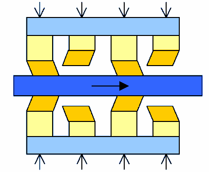
Slew mode motion begins and ends with zero control voltage on all piezo elements. This means that when powered down, the runner is held in place by the friction resulting from the high internal preload and can only be moved from its position by very high external forces.
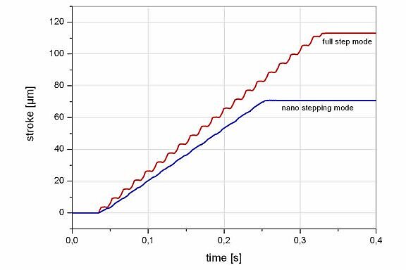
In some applications, the discontinuities of the stepping motion described above can lead to undesirable oscillation of parts or assemblies. In such cases, it is possible for the slew mode controller to overlap the shear motion with the toggling of the clamping piezos, so that the piezos always clamp and unclamp the runner as it moves at a constant velocity. The operational compromise to obtain constant velocity slewing is lower force and step size compared to the full step slew mode.
2.3 Dynamic Park/Position Hold Mode
With the ability to slew and dither the Nexline actuator, another mode of operation can be realized. Upon a power off condition, the Nexline drive is programmed to remember it’s position, and by adjusting the voltage applied to the clamp and shear piezo actuators, it will hold it ’s exact position at the moment of the power off condition even as the PZT actuators discharge from their operating voltage to a zero volt condition.
This mode can also be implemented when the Nexline is in operation by commanding it to hold position while auto zeroing its bias voltage from programmed set points. Maintaining an average low bias voltage greatly extends the operational lifetimes of the Nexline actuator since PZT ceramic lifetime is proportional to the average operating bias voltage.
3. Application
This technology was originally developed for applications in the semi -conductor industry. There, heavy, extreme precision optics assemblies, weighing 10’s of kg, must be positioned vertically and aligned in multiple axes with nanometer resolution. The coarse positioning requirements are for quasistatic motion over several millimeters to compensate for the relatively large mechanical tolerances in the manufacturing of machine components and structures. The fine positioning requirements, however, entail motion over a few microns with subnanometer resolution and sufficient bandwidth to also compensate for vibrational disturbances.
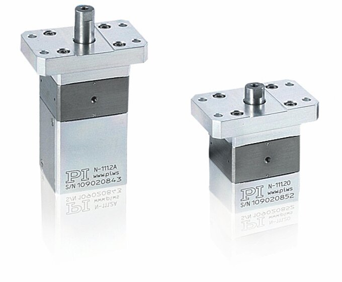
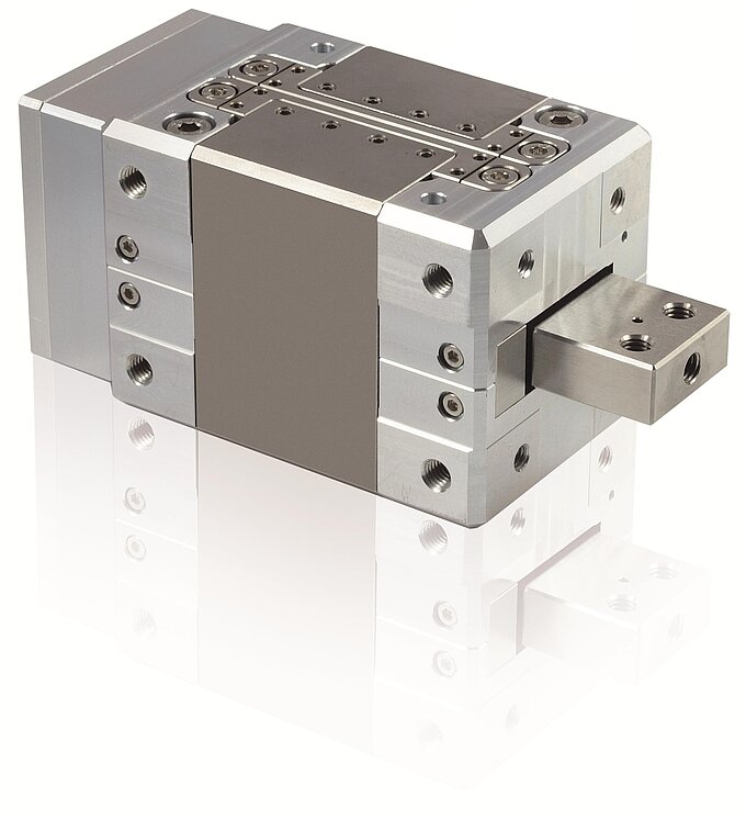
A significant requirement is that once on target, the position must be held with nanometer accuracy without having to apply voltage to the piezo elements. Fig 3.2 shows a linear actuator which meets the requirements listed above.
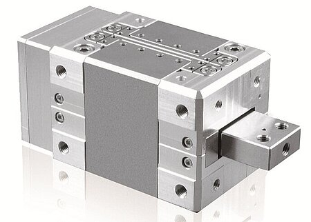
N-216 Operational Specifications:
- Up to 20 mm stroke
- 50 picometer resolution
- +/– 800 N ( 180 lb.) push/pull capability
- Actuator mass 1.2 Kg Actuator volume –340cc Stiffness – 45 N/micron
- Dynamic range over 2mm travel – >10,000,000
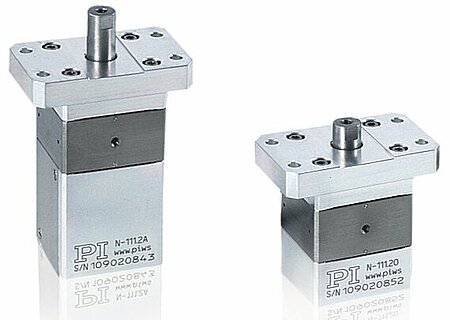
Also shown is a miniature version capable of 1.5 µm steps and forces to 50 N (see Fig 3.1).
In contrast to classical linear actuators, a number of components, such as leadscrew, gearbox, and bearings, can be dispensed with because the linear motion is generated directly. This makes it possible to realize very compact, low mass, high -load devices. Fig 3.3 shows a UHV-compatible hexapod made with fully nonmagnetic NEXLINE® actuators. Fig 3.4 shows a larger non-magnetic model for a complex alignment application involving superconducting magnets.
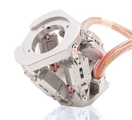
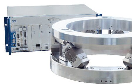
NEXLINE® actuators can be designed for a wide temperature range and are intrinsically vacuum compatible. Because of the temperature dependence of the piezo effect, the displacement of the individual piezo elements is reduced to about 30% at cryogenic temperatures. The maximum operating temperature of the PZT ceramics is about 120°C due to effects of thermal depoling.
4. Test Results
The performance of the actuators is proportional to the amount of shear piezos and the driving voltage applied to it. Fig 4.3 compares holding force vs. step size of several actuators. Fig 4.1 shows the smoothness of motion in full-step mode and nano-step mode. In slew mode, the maximum step size is about 6.5 µm. The maximum speed is proportional to the step frequency, which is generally limited by the controller used and by the amount of power available. Normal speeds are between a few hundred microns and a few millimeters per second. Reducing the amplitude of the voltages on the shear piezos results in smaller step sizes. The minimal reproducible step sizes are limited from 5nm to 10nm. This is determined by the surface microroughness of the contact areas, and by parasitic piezo movement due to the intrinsic non linearities in the piezo material.
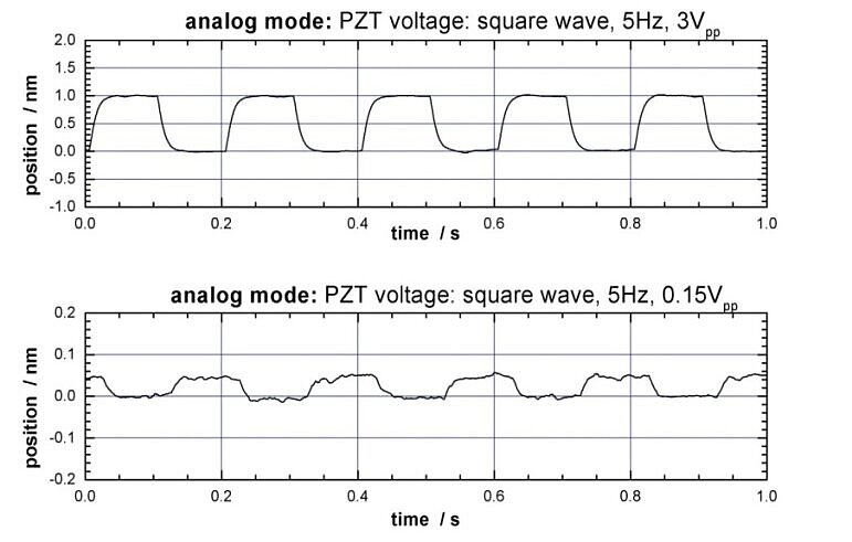
Similarly, in dither mode, a reduction of the maximum control voltage swing will result in a decrease of the analog mode stroke. Fig 4.2 shows measured values for the motion of the runner of about 1 nm in response to 3 V square-wave signal. The resolution limit could not be determined, because the resolution of the capacitive sensor which was used was only about 50 pm.
As the force opposing the motion of the actuator is increased, the step size can be seen to decrease to zero. The reason is the elastic deformation of the piezo elements and the connecting structure, which leads to motion loss when the clamping piezos toggle. The maximum force which the actuator can withstand using maximum shear piezo control voltage amplitudes is called the blocking force and is between 300 and 800 N for off-the-shelf actuators.
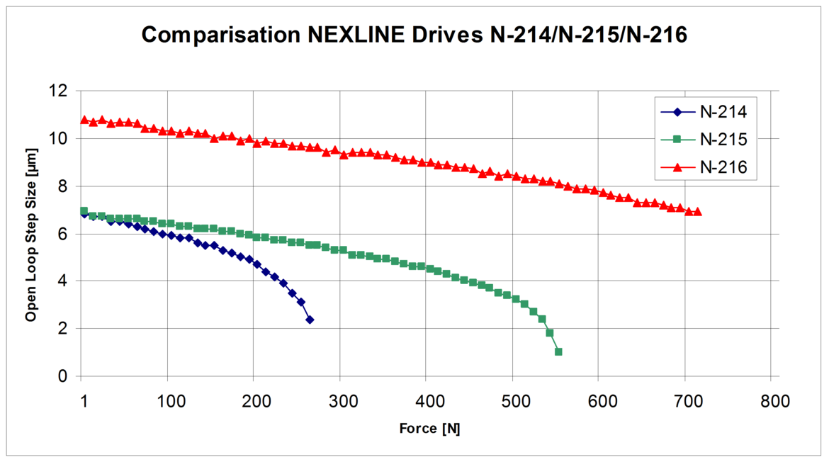
In the face of very high opposing forces — forces exceeding the normal preload times the friction coefficient — the runner would slide between the piezo actuators clamps (analogous to a slip clutch effect) and be driven to the mechanical hard stop. Those forces would need to be greater than 800 N for the N-216 model.
5. Conclusion
The development of the piezoceramic linear motors described here demonstrates that it is possible to combine long travel ranges, ultra -high resolution, and high force in a unified drive design. This drive additionally due to its high stiffness can move heavy loads dynamically. The drive is intrinsically self-locking and does not expend energy to hold a position. This development, as noted earlier, was undertaken for applications in the semiconductor industry, and multiple units in our lifetime test facility have demonstrated lifetimes of >108 slew and >109 dither mode cycles to date in continuing durability tests. The lifetime design goal of these actuators is 10 years in a vacuum environment. More testing is necessary for cryogenic applications and for mountain top observatory environments. From our experiences in extreme industrial applications, a simple and low cost dry air purge of a few cc’s per hour will ensure long actuator lifetime for ground based observatory environments.
The applications for ground and space astronomical telescopes with their associated instrumentation packages range from primary mirror segment positioning, active truss structures, and embedded coarse/fine position control in space constrained instrument packages. From a cost standpoint, NEXLINE actuators are higher in cost than conventional micropositioning drives. Yet when the requirement demands coarse/fine position control with nanometer level resolution, they are cost competitive, simpler to integrate, and occupy much less volume and mass than equivalent force hybrid mechanical actuation designs.
References
1) K. Lorell et al; “Design and preliminary test of precision segment positioning actuator for the California Extremely Large Telescope”, Proceedings of the SPIE, Volume 4840, pp. 471-484 (2003).
2) United States Patent 6,800,984, “Piezo linear drive with a group of piezo actuator stacks as well as method for operating such a drive”, October 5, 2004.
3) Pitz, E. et al; “Five –axis secondary system for UKIRT”, Proc SPIE Conf. on Advanced Technology Optical Telescopes V”, ed. L.D. Barr, 2199, 516–522, 1994.
Blog Categories
- Aero-Space
- Air Bearing Stages, Components, Systems
- Astronomy
- Automation, Nano-Automation
- Beamline Instrumentation
- Bio-Medical
- Hexapods
- Imaging & Microscopy
- Laser Machining, Processing
- Linear Actuators
- Linear Motor, Positioning System
- Metrology
- Microscopy
- Motorized Precision Positioners
- Multi-Axis Motion
- Nanopositioning
- Photonics
- Piezo Actuators, Motors
- Piezo Mechanics
- Piezo Transducers / Sensors
- Precision Machining
- Semicon
- Software Tools
- UHV Positioning Stage
- Voice Coil Linear Actuator
- X-Ray Spectroscopy

