In a high-precision positioning system, improving the stage, sensors, or controller only gets you so far. Eventually, vibration from the surrounding environment becomes part of the positioning error budget.
How that vibration reaches sensitive equipment depends strongly on how the system is mounted. A softer mount can isolate floor vibration, but it also makes the equipment more susceptible to forces acting directly on it. An ultra-stiff mount provides excellent positional stability and low sensitivity to direct disturbances, but more vibration can be transmitted from the floor or supporting structure. There is no simple passive solution that does both jobs equally well. That is where active vibration control (AVC) becomes interesting.
Engineers at PI investigated how AVC could improve this trade-off for an ultra-stiff piezoelectric mount. The idea is to retain the stability of a stiff mechanical connection while using active control to reduce vibration dynamically. Vibration in the range from 0.2 to 2,000 Hz was evaluated using power spectral density and cumulative power spectrum measurements of position, velocity, and acceleration. Online controller optimization reduced the cumulative power spectrum by up to 99.5% in the single-axis test setup. The approach is extended to a six-degree-of-freedom piezo hexapod for multi-axis active vibration cancellation.
Separating the Disturbance Paths
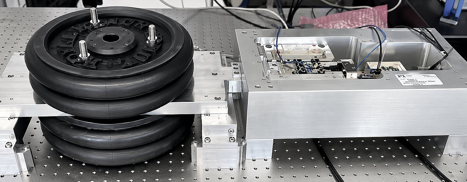
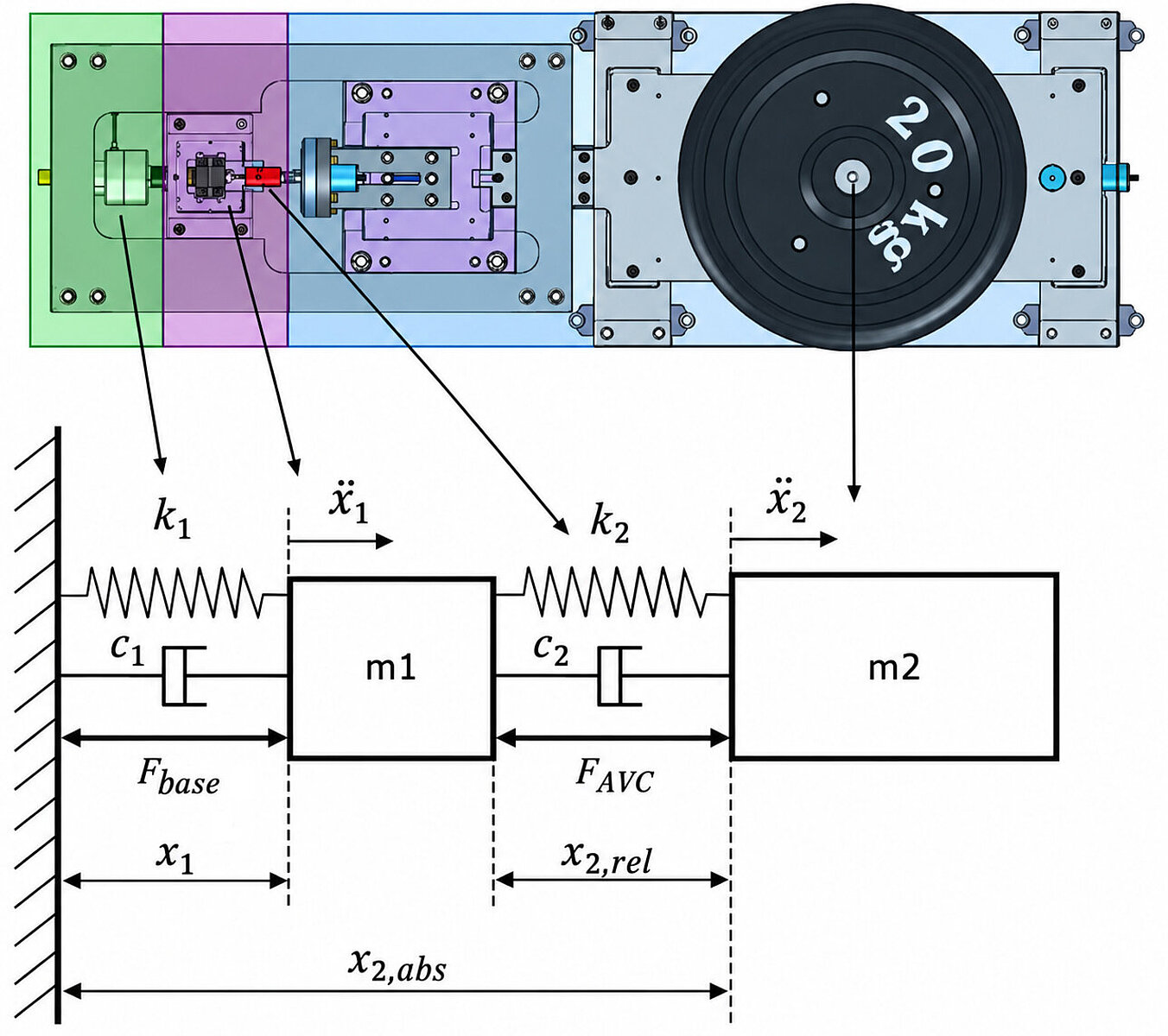
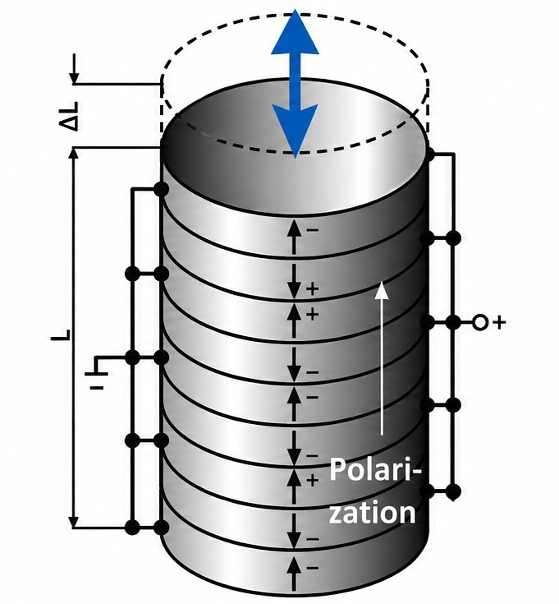
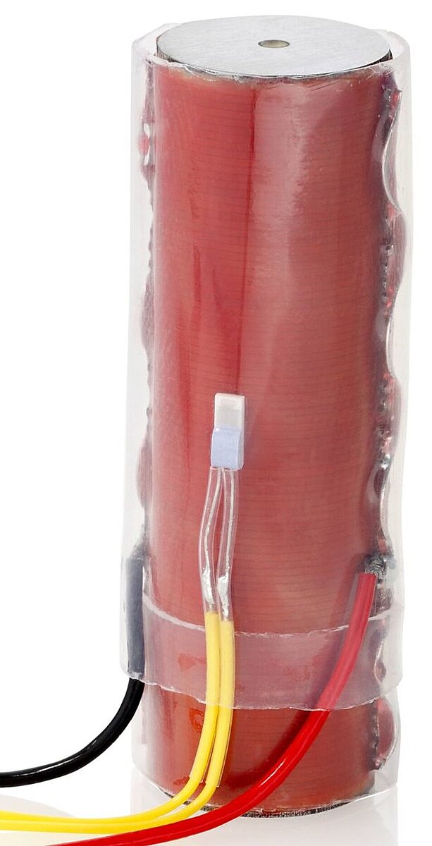
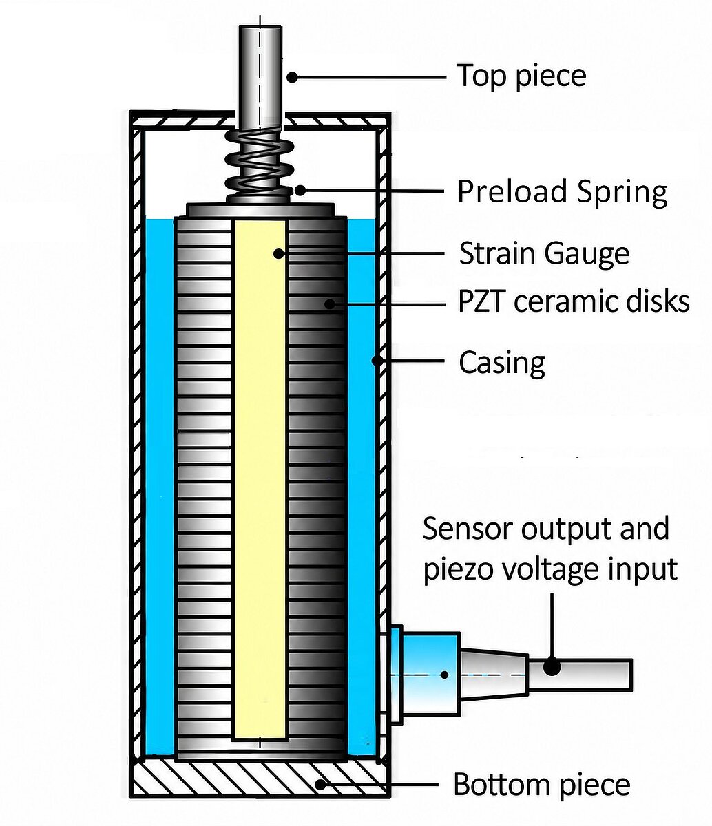
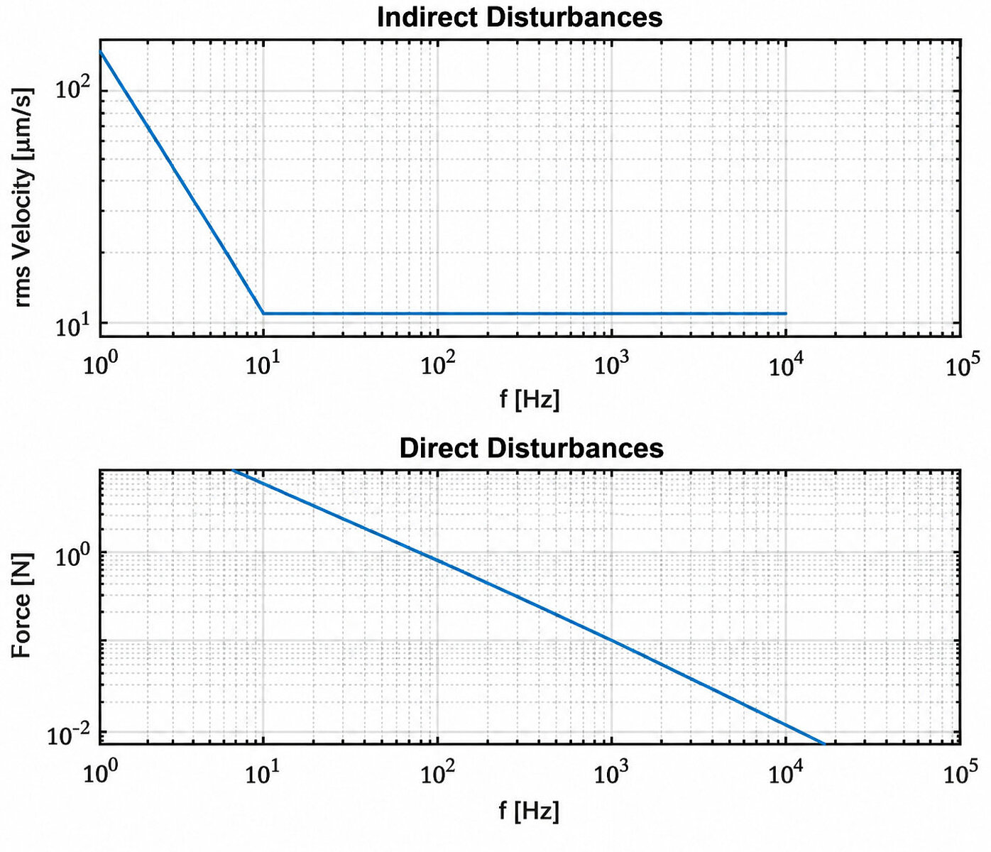
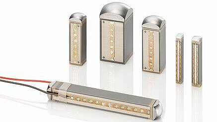
The single-axis setup represents the sensitive equipment as one mass and its supporting floor as another. A preloaded multilayer piezo actuator (P-843.20) connects them and serves as the active mount. This actuator is equipped with strain gauge sensors and can generate push forces to 800N and pull forces to 300N. A high-force piezo actuator (P-235.1S), also with internal preload, excites the support to simulate floor vibration. Direct disturbances are introduced separately through a second virtual axis of the low-voltage actuator. Position sensors and accelerometers measure how both masses respond. From these measurements, the system evaluates position, velocity, and acceleration. This arrangement lets us evaluate floor vibration, direct-force disturbances, and their combined effect under controlled conditions. For the floor excitation, the tests use the VC-C vibration criterion, described in the study as a good standard for lithography and inspection equipment in the semiconductor industry.
Feedback, Feedforward, or Both?
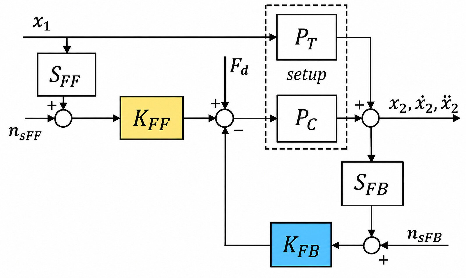
The team compared several position-, velocity-, and acceleration-based feedback methods, as well as position feedforward combined with velocity bandpass feedback. The two control concepts address the vibration problem differently.
Feedback responds to measured motion of the system and can be used to damp resonance modes.
Feedforward uses information about an incoming disturbance to suppress the disturbance before it reaches the sensitive equipment. This distinction matters because a controller that performs well against floor vibration may not be the best choice for a force acting directly on the equipment. For that reason, each approach using position, velocity, and acceleration was evaluated rather than judging its effectiveness by resonance attenuation alone.
Measuring Vibration Across the Frequency Range
Looking only at a resonance peak does not tell the whole story. The tests therefore evaluate vibration in both the time and frequency domains. The primary performance metric is the cumulative power spectrum (CPS), calculated by integrating the power spectral density over the frequency range from 0.2 Hz to 2,000 Hz.
In practical terms, CPS provides a way to evaluate the accumulated vibration error across the relevant frequency range instead of focusing on a single frequency. Rather than manually tuning every controller configuration, an optimization routine was used to minimize the CPS of position, velocity, acceleration, or a weighted combination of these quantities. Stability and robustness criteria were included in the optimization, and the resulting controller parameters were verified on the physical test setup.
Which Control Strategy Worked Best?
Unsurprisingly, there was no single control strategy that performed best under every disturbance condition. Nearly all tested approaches improved performance compared with open-loop operation. Overall, acceleration- and velocity-based active vibration cancellation performed better than the position-based approaches, with Velocity Bandpass Filter feedback providing the best overall performance across the cases studied.
The strongest isolation result occurred when floor vibration was the dominant disturbance and position feedforward was combined with Velocity Bandpass Filter feedback. Under pure floor disturbances, the position CPS was reduced to approximately 0.5% of its open-loop value, corresponding to a reduction of about 99.5%.
Importantly, that result is specific to the single-axis test setup, applied disturbance spectrum, and optimized controller settings. It should not be interpreted as a vibration-reduction figure that can automatically be assumed for every machine or installation.

The results also show why selecting the controlled variable matters.
- For floor disturbances, the CPS ranking was: velocity < acceleration < position.
- For force-dominated disturbances, the ranking changed to: acceleration < velocity < position.
The preferred control variable therefore depends on the disturbance spectrum in combination with the mechanical response of the system.
Transmissibility and Compliance Tell Different Stories
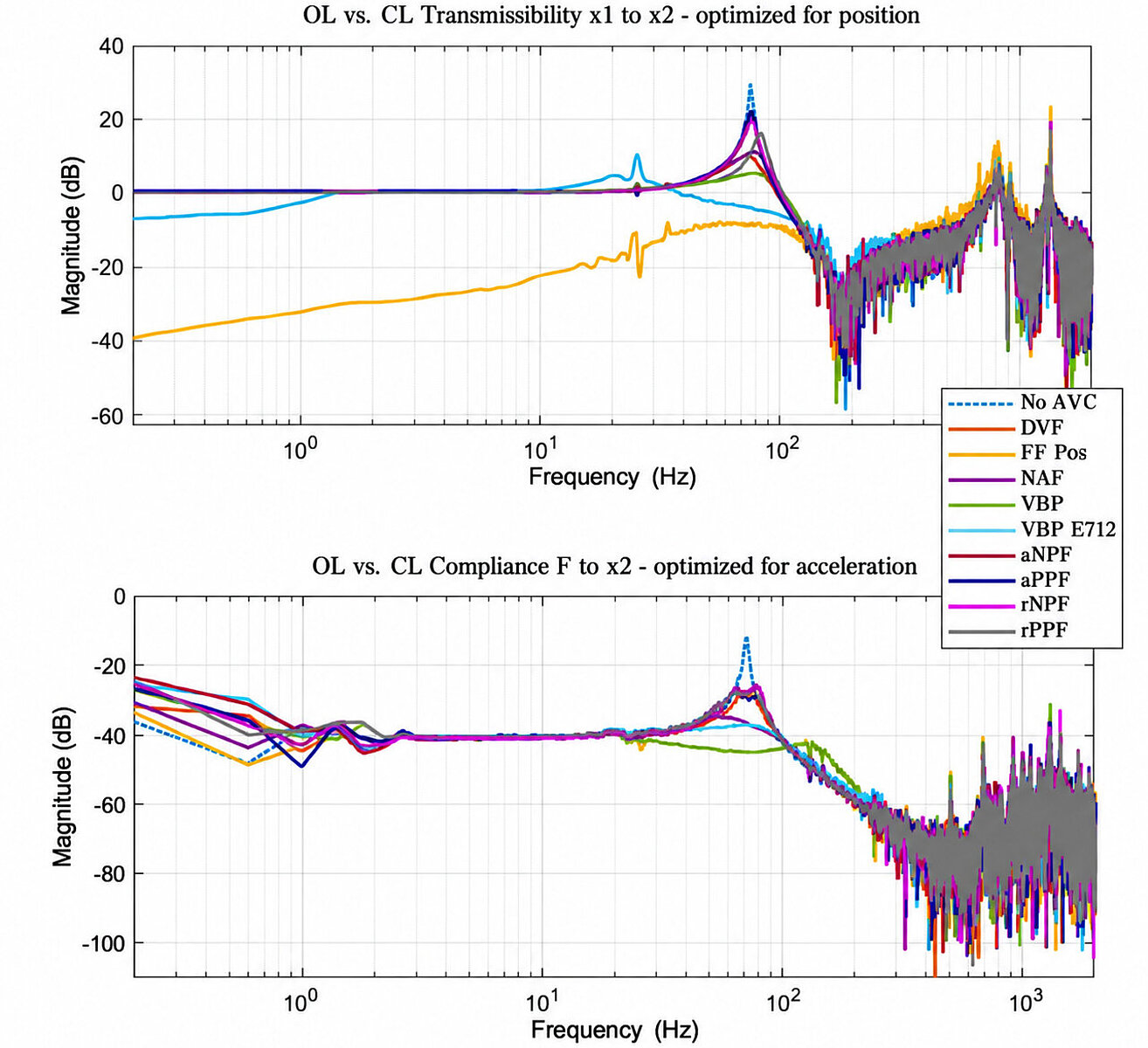
The distinction between floor vibration and direct-force disturbances becomes clearer when looking at transmissibility and compliance. Transmissibility describes how motion from the supporting structure reaches the sensitive equipment. Compliance describes how the equipment responds when a force acts directly on it.
With position feedforward, transmissibility shifted downward by approximately 40 dBup to, and in some cases beyond, the resonance frequency of the test setup. This produced effective isolation of the sensitive mass from floor disturbances. However, the compliance behavior was different. Because position feedforward uses only the motion of the supporting mass, its compliance corresponds to the Velocity Bandpass Filter feedback approach. This reinforces one of the central findings of the test: there is no universally best AVC configuration. The appropriate strategy depends on which disturbances dominate and which motion variable matters most to the application.
From One Axis to Six
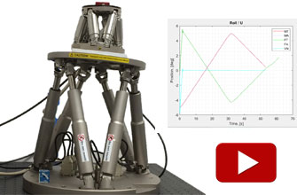
The next step is transferring these findings to a six-degree-of-freedom piezo hexapod system.
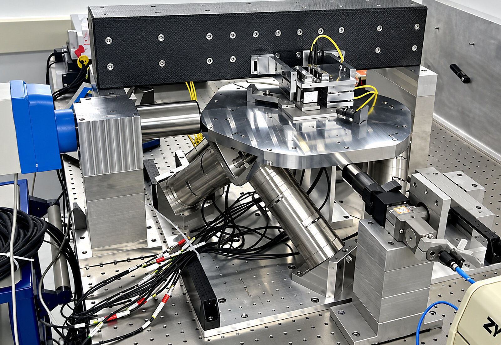
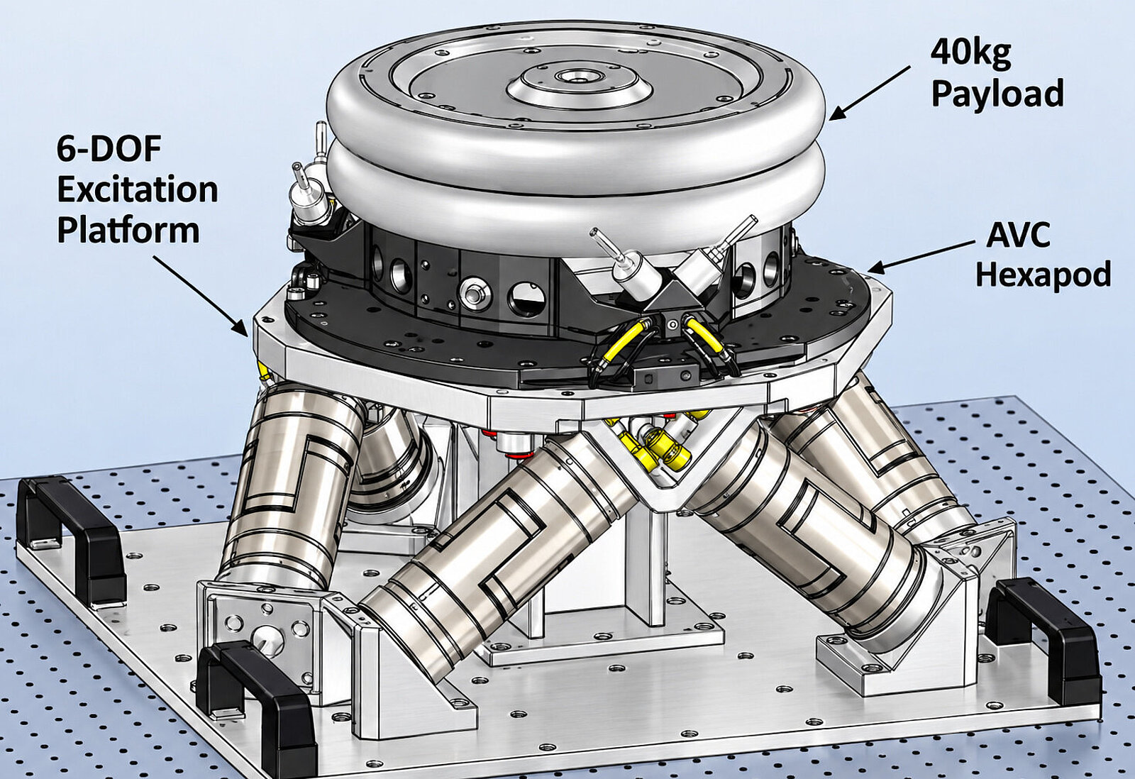
A dedicated high-force piezo excitation platform has been developed to introduce indirect disturbances in six axes, together with a more compact multilayer piezo-based AVC hexapod intended for multi-axis active vibration control. The performance figures discussed above come from the single-axis tests. The six-axis system is being commissioned and represents the next stage of the work.


Blog Categories
- Aero-Space
- Air Bearing Stages, Components, Systems
- Astronomy
- Automation, Nano-Automation
- Beamline Instrumentation
- Bio-Medical
- Hexapods
- Imaging & Microscopy
- Laser Machining, Processing
- Linear Actuators
- Linear Motor, Positioning System
- Metrology
- Microscopy
- Motorized Precision Positioners
- Multi-Axis Motion
- NanoAutomation
- Nanopositioning
- Photonics
- Piezo Actuators, Motors
- Piezo Mechanics
- Piezo Transducers / Sensors
- Precision Machining
- Semicon
- Software Tools
- UHV Positioning Stage
- Voice Coil Linear Actuator
- X-Ray Spectroscopy