Stepper Motor Basics
Many processes in production, automation, and research rely on precisely moving, adjusting and aligning tools, optics, and components.
Precision positioning equipment, based on a rotating electric motor and some kind of screw drive or worm gear drive to transfer and convert the output at the motor shaft into motion at the positioning actuator or stage, is widespread in the industrial sector. Stepper motors are considered robust, cost efficient, and provide a long service life. They provide high torque even at low speed, and are easy to control.
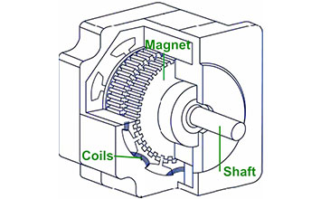
Stepper motors take discrete positions of constant distance. The most common stepper motors are two phase / four phase motors with 200 to 500 full steps per revolution. Advanced controllers can interpolate thousands of microsteps between each full step to achieve higher resolution. A controller commands a position by issuing a number of electric pulses. Position feedback is not required, but can help to improve performance. If no position feedback is used, parameters such as maximum acceleration have to be considered to avoid stalling the motor during acceleration. A mechanical damper on the motor shaft, which also works as a handwheel, supports smooth running and helps to achieve better dynamics. A combination of suitable linear measuring systems and high-resolution controllers increases the positioning repeatability.
Stepper motors can hold a position very stable, without jitter, but current must be applied continually unless brake mechanisms or self-locking gearboxes / screw drives are used. Stepper motors can heat up during (continuous) operation and this must be taken into account when designing a system.
Precision Positioning, Down to the Nanometer Range
A linear positioning stage equipped with a 2mm lead screw, driven by a stepper motor with 200 full steps (1.8° per step) provides linear motion in 10µm increments for each motor step. This is hardly considered precision motion in the 21st century and microstep controllers can improve the performance considerably. A simple microstepper with 16 microsteps already brings this number down into the sub-micron range at 0.625µm and 39 nanometers are calculated for a 256 interpolation factor. Bear in mind, low friction mechanics are required to achieve this calculated resolution in the real world.
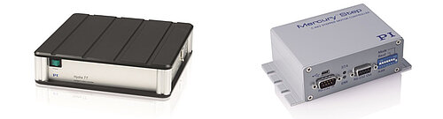
Higher interpolation means smoother motion and better resolution and economical controllers such as the C-663.12 Mercury Step already provide 2048 microsteps. Advanced controllers, such as the SMC Hydra, provide virtually continuous, step-less behavior similar to a brushless motor. In addition to higher position resolution, dynamic velocity, and acceleration range, vibrations that are present in full step mode are now virtually absent.
Coupled to a high-precision, low friction mechanical positioning stage, stepper motors can achieve linear resolution in the nanometer range, even when operating without the help of position feedback such as a linear encoder.
Position Feedback Improves Repeatability and Linearity
Position feedback, in the form of a direct-measuring linear encoder can further improve the accuracy and repeatability. Drive train errors caused by backlash and friction in the drive screw, gear-box or the guiding system are now seen by the controller and can be compensated for.
Stability and Resolution of Closed-Loop Steppers Compared to Servo Motors
Position-controlled stepper motor axes are known for excellent in position stability. Traditional classical (DC) servo systems exhibit typical controller oscillation up to a few encoder counts. For low-friction, low-damping situations, this can lead to instability if the servo parameters are not set carefully.
A typical servo system feeds off errors, i.e., it needs to see an error before it reacts. These effects do not occur with a stepper motor, because it does not need the servo to maintain a stable position. Actually, when a current is applied to the stepper motor, it creates a moment that keeps it in place, while a servo motor wants to move the moment a current is applied. Stepper motor controllers provide an intrinsic velocity feedforward, which allows them to run at extremely constant velocity, even at very low speeds, without the help of an additional tachometer.
However, if the microstep resolution of the controller is too low, a disparity between the motor and the encoder resolution can lead to a quantization of the achievable positions. In case of the SMC controller with 3000 microsteps, the angular motor positions are virtually continuous – for a 1mm drive screw, the calculated resolution is 1.6 nanometers- typically below the achievable resolution of a positioning stage with mechanical bearings.
Step-and-Settle Behavior
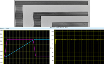
Good step-and-settle behavior is important for high throughput and time critical processes. In addition to the mechanical design, the control algorithms have a strong influence on the performance. SMC controllers suppress high frequencies and still allow dynamic positioning with minimal overshoot, eliminating oscillations and side effects for the overall system stability.
The mass of the payload, the resulting moments, and the orientation of the motion axis must be taken into account when optimizing the control parameters. Further measures are not necessary; the system is stable, and optimized dynamically.
Constant Velocity at Low Speed Motion
Velocity is a decisive parameter for selecting a positioning system. Often, the highest speed is what counts, but, some applications require particularly slow constant motion. In some scientific applications, velocities can range from a few 100µm/sec to considerably less than 100nm/sec, corresponding to a feed of a few millimeters per day. To achieve very uniform motion, a positioning system with a resolution around one nanometer is recommended.
Influence of Microstep Count on Noise and Position Deviation
The number of microsteps in a controller has an influence on the smoothness of motion. A higher microsteps count leads to better velocity constancy and lower vibrations.
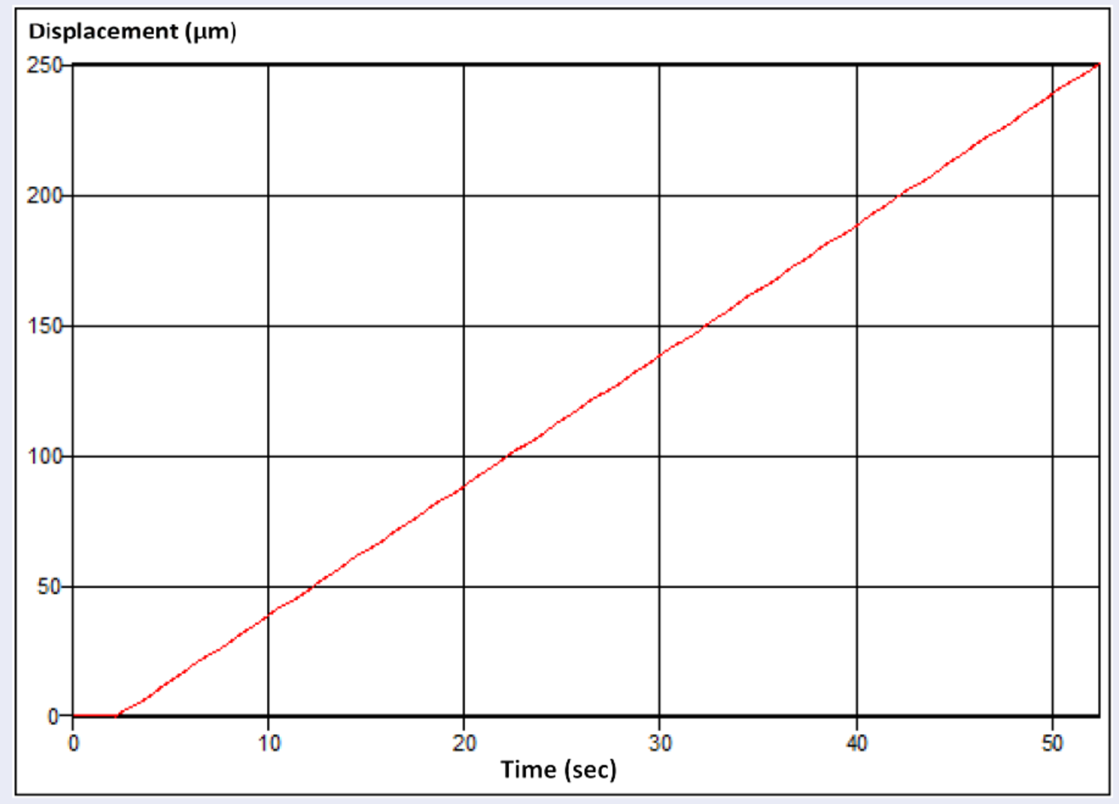
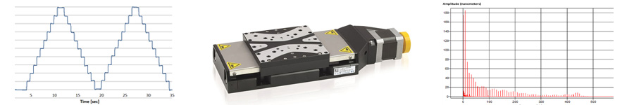
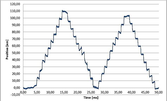
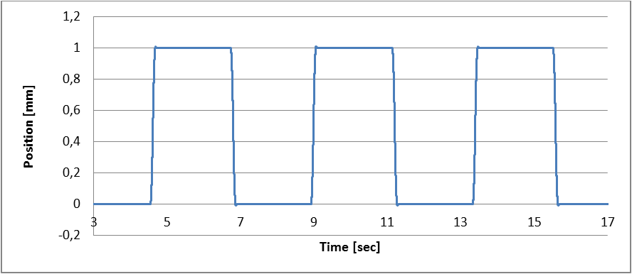
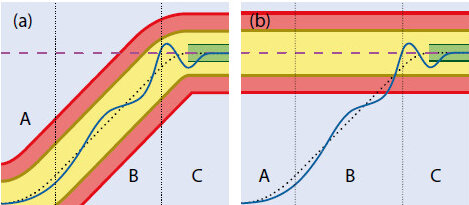
Shown above, constant velocity at 5 µm/sec (open loop). L-511 linear stage with SMC Hydra motion controller (3000 microsteps per full step). At this low-detail level, the performance with a 16 microstep controller looks nearly identical. (Image: PI miCos)
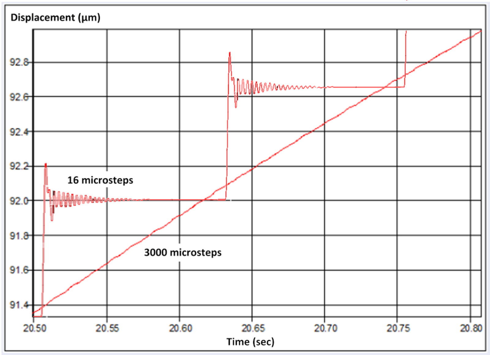
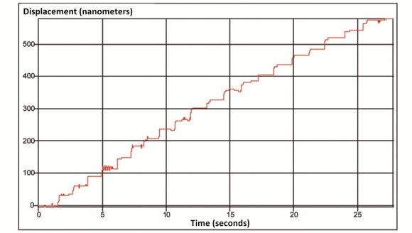
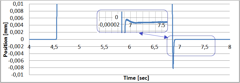
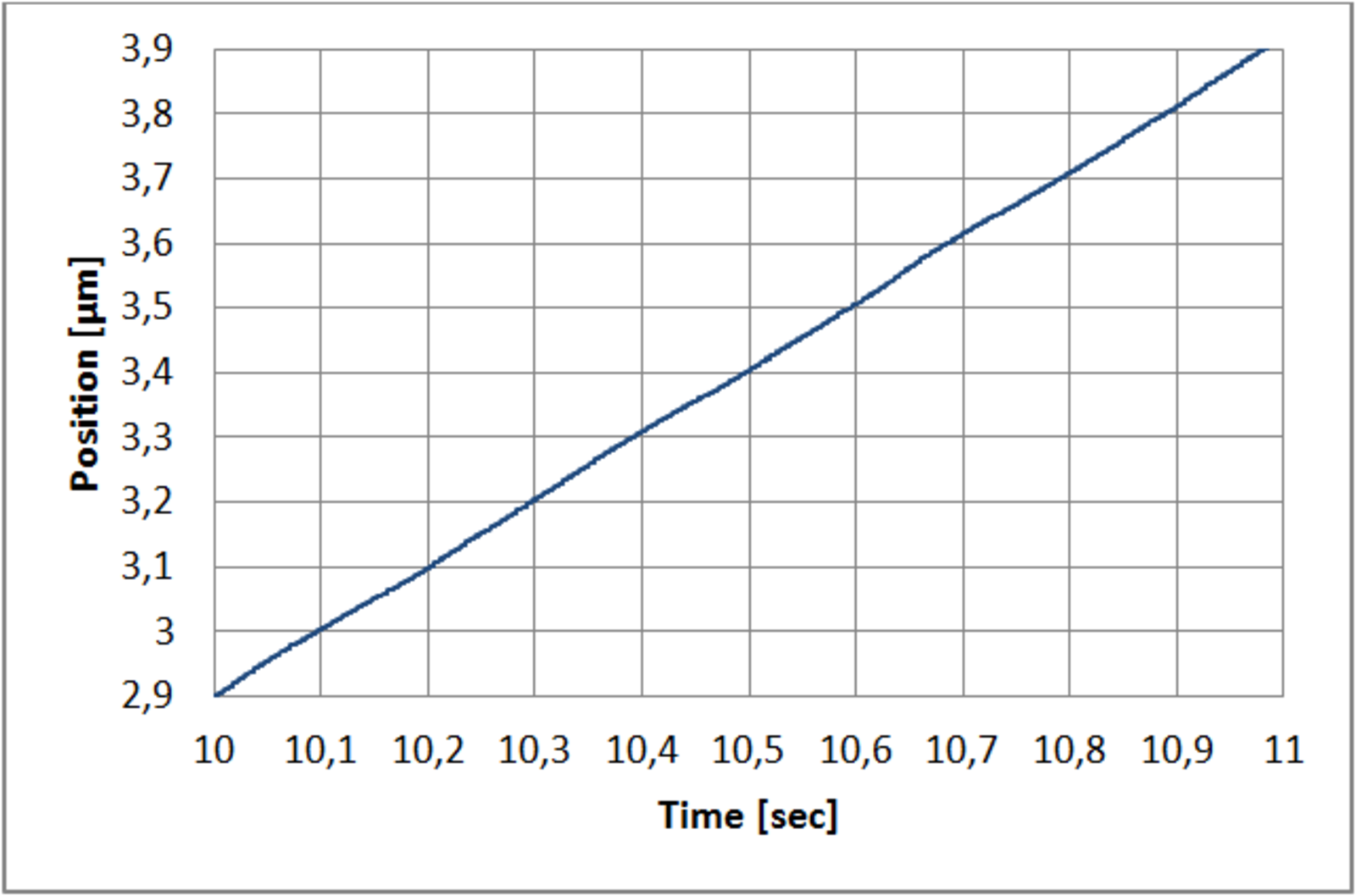
Shown above, this detailed view shows a big difference. The 16 microstep controller cannot resolve below 0.6 microns and each step is clearly visible at this resolution. The 3000 microstep controller performs smooth motion with almost perfect straightness. Tests in closed loop operation have shown additional improvements. (Image: PI miCos)
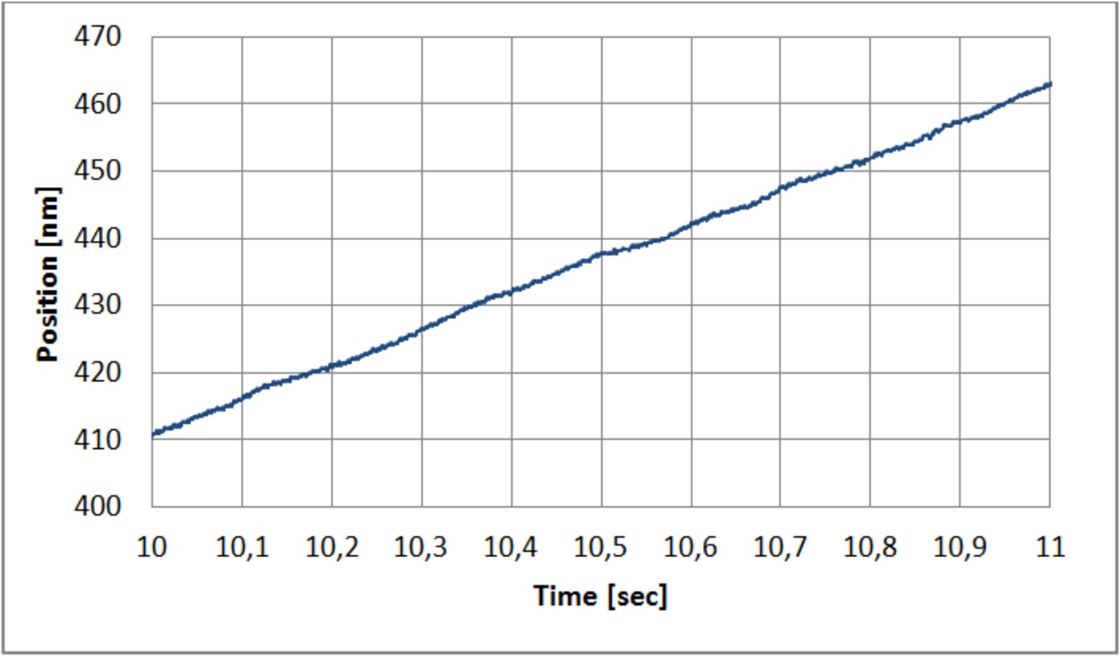
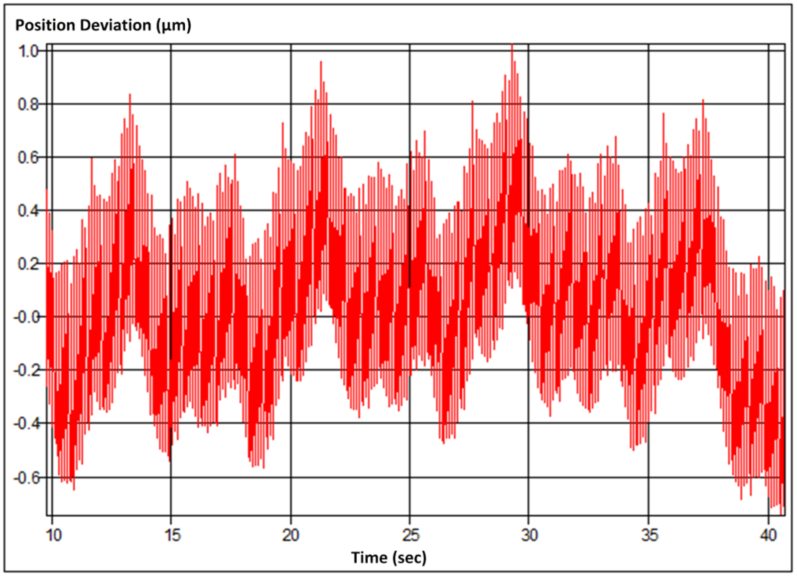
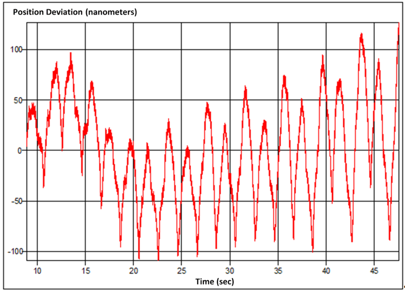
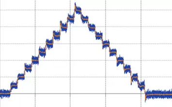
Shown below, 16 microstep performance in constant velocity mode (open loop): position deviation compared to ideal target position based on constant velocity. Note, the peak-peak deviation is only 1.5µm. The controller’s limited resolution of 0.6µm is largely responsible for behavior shown below. (Image: PI miCos)
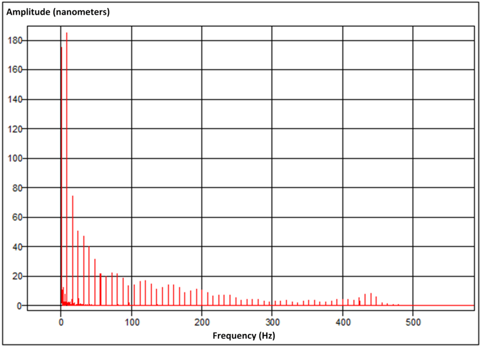
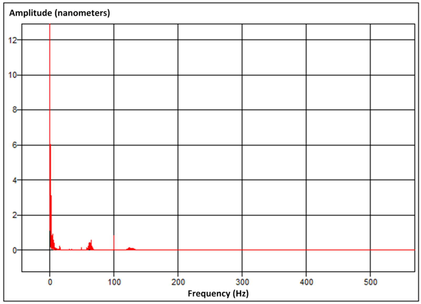
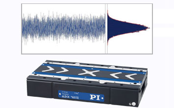
Shown above, FFT: Frequency spectrum of the position deviation of the 16 microstep controller (Image: PI miCos)
Show above, position deviation compared to ideal target position based on constant velocity with 3000 microstep controller (constant velocity mode, closed-loop): the high resolution microstep controller shows significantly improved performance compared to the 16 microstep behavior. (Image: PI miCos)
Shown below, FFT: Frequency spectrum of the position deviation of the 3000 microstep controller (Image: PI miCos)
Dynamic Position Correction (Error Mapping)
Error mapping (dynamic position correction) is a common technique to improve the overall accuracy of linear and rotary positioning stages. Improvements up 1000% are feasible.
For this purpose, the deviation from the target position at a predefined step size is measured with a reference measuring system. The measured deviations are stored in a table inside the controller. During operation, the controller dynamically applies the information gathered from the reference system and applies a correction factor for each target position correcting the motion profile on the fly.
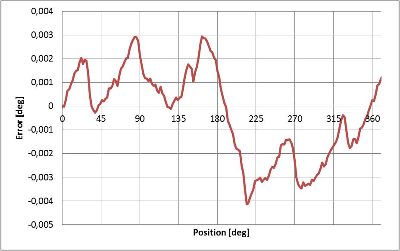
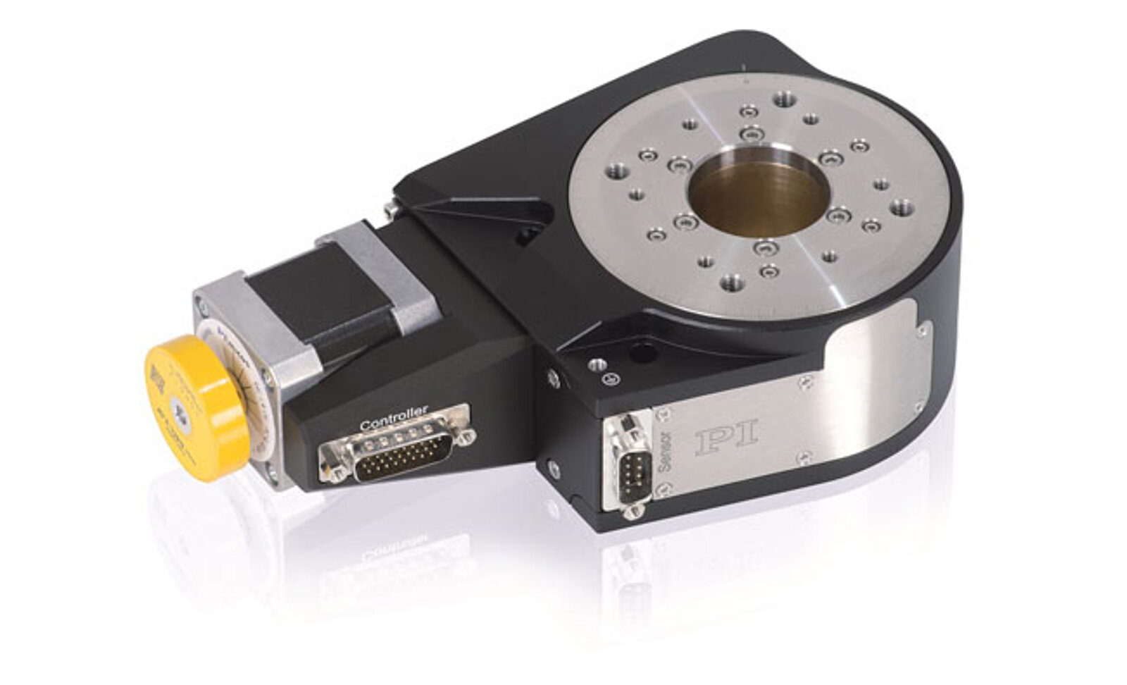
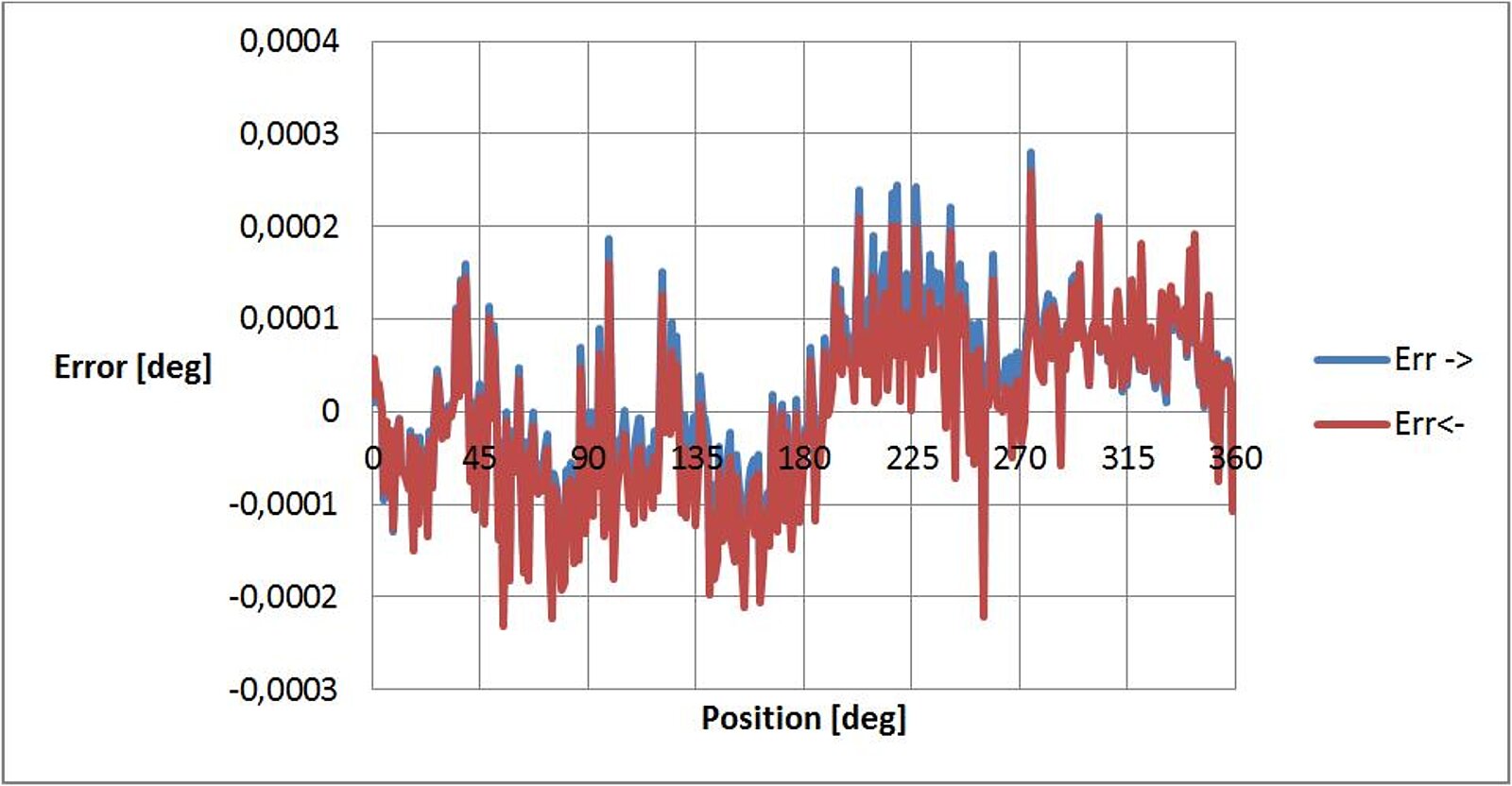
Shown above, the absolute accuracy of a closed-loop L-611 / PRS-110 rotation stage (below) with stepper motor and angle-measuring system, recorded over 360 individual positions spaced at 1°. The maximum angular error amounts to ±0.004°. (Image: PI miCos)
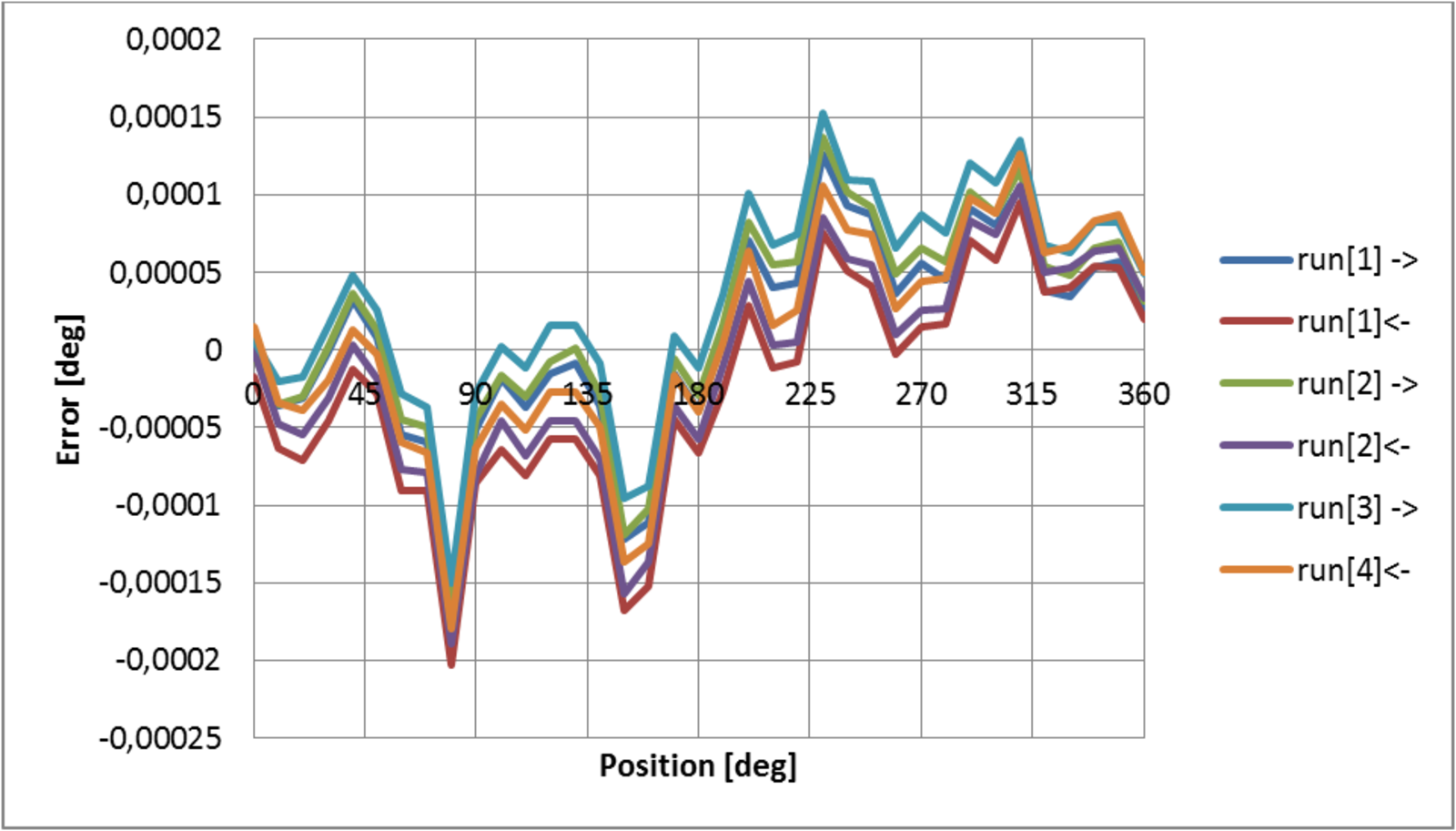
Shown below, the same stage as before, but with an active error map stored in the SMC Hydra controller for dynamic error correction. The symmetrical behavior independent of the direction of rotation is clearly visible. The maximum angular error is reduced to ±0.0003°. (Image: PI miCos)
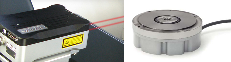
Measurement Set-Up, Ambient Conditions, Test Equipment
All measurements were performed under standard lab conditions, temperature 22°C ±1°C, humidity 43% ±3%. A vibration isolated table was used, but no additional isolation from thermal, acoustic or other external influences. Ambient conditions can have a strong influence on the achievable precision. For a typical positioning stage made of aluminum, a 0.01°C fluctuation of the ambient temperature is equivalent to a position change of 10nm. A stable environment is basic requirement for precision motion in the sub-micrometer range. The user of special material pairings can help, too.
The following measurement equipment was used:
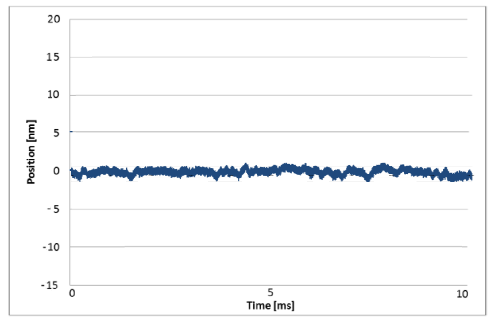
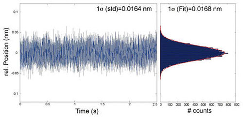
Shown above, the position noise of an L-511 linear stage, with energized motor, driven by the SMC Hydra controller in closed-loop mode. The noise level is at approximately 3 nm (peak-peak, 10 kHz sample frequency, unfiltered) which can be attributed to the interferometer and environment during the time of the measurements. (Image: PI miCos)
Positioning Systems and Motion Controllers
The following standard linear and rotation positioning systems and controllers were used for the above tests.
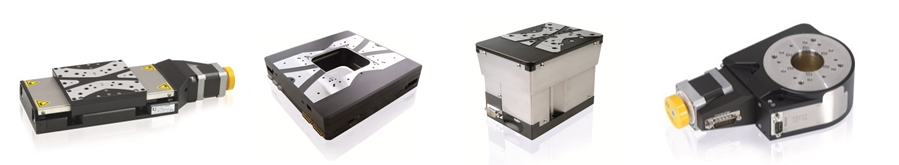
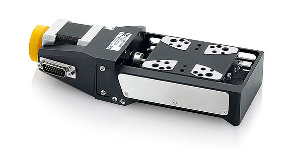
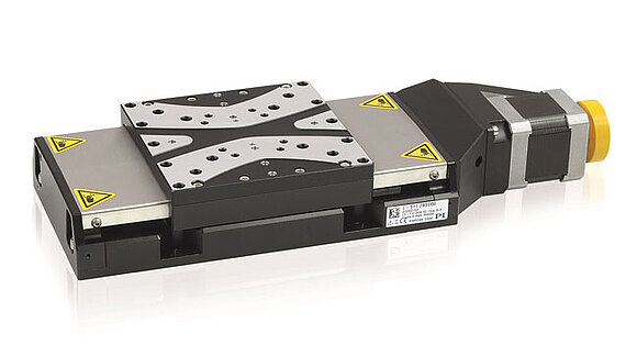
- L-511 Linear Stage (formerly LS-110) open and closed-loop versions
- L-509 (formerly PLS-85) open and closed-loop versions
- L-611 (formerly PRS-110) open and closed-loop versions


Blog Categories
- Aero-Space
- Air Bearing Stages, Components, Systems
- Astronomy
- Automation, Nano-Automation
- Beamline Instrumentation
- Bio-Medical
- Hexapods
- Imaging & Microscopy
- Laser Machining, Processing
- Linear Actuators
- Linear Motor, Positioning System
- Metrology
- Microscopy
- Motorized Precision Positioners
- Multi-Axis Motion
- Nanopositioning
- Photonics
- Piezo Actuators, Motors
- Piezo Mechanics
- Piezo Transducers / Sensors
- Precision Machining
- Semicon
- Software Tools
- UHV Positioning Stage
- Voice Coil Linear Actuator
- X-Ray Spectroscopy