Moonshots, Mine Carts, and Million Mile Motion Stages
A look at lifetime expectation of Precision Motion Stages compared to Performance Automobiles
Long-distance motor racing has been established as a battleground where engineers fight for the best balance of performance and longevity and brands can build trust in their operations and products. And while R&D and manufacturing engineers work hard to blend art, science, and engineering that fuel the fascination of millions of performance automobile enthusiasts around the world with the latest technologies – including hybrid and fully-electric drive trains – their colleagues in industrial precision motion control work just as relentlessly to push the limits of the possible. Their success is usually not crowned with trophies, despite the incredible performance of modern precision motion systems, such as the ones employed in the industrial production of cutting-edge chip technology.
Here, tolerances are often measured in nanometers as Moore’s Law keeps asking for smaller and smaller feature sizes with every new chip generation. Tolerances on modern high-performance engine parts are also continuously shrinking and moving towards the micron realm. Yet, despite output and efficiency are reaching new heights, durability concerns often persist. For many performance car enthusiasts, the portent of 100,000 miles on the odometer signals a point of departure and concern for future reliability.
Imagine though, if we re-calibrated our expectations to 500,000 or even 1,000,000 Miles.
Load and Inertia are the Enemy: The Parallels of Precision Automation and Performance Cars
Precision automation systems share an uncanny similarity to high-performance sports cars. The parallels of dynamic performance, cornering, stiffness, precision stopping (step-settle), and weight are combined with micron and sub-micron scale tolerances for repeatability and trajectory following. In both cases and in similar fashion at scale, the operating life of car engines and motion systems is similar. It is common knowledge that higher RPM operation of a reciprocating engine stresses materials and increases the load on the bearings in a non-linear manner that significantly affects lifetime. As a consequence, high revving race engines, despite employing the highest quality materials, the most sophisticated design and production techniques, and highest standards of quality control, have a significantly shorter service life between rebuilds compared to their low RPM siblings, employed in everyday utility or transportation applications.
Before we look at the relation of load and lifetime in precision linear motion stages such as the ones used in high performance automation applications, it’s worth taking a journey to Germany in the 1820s.
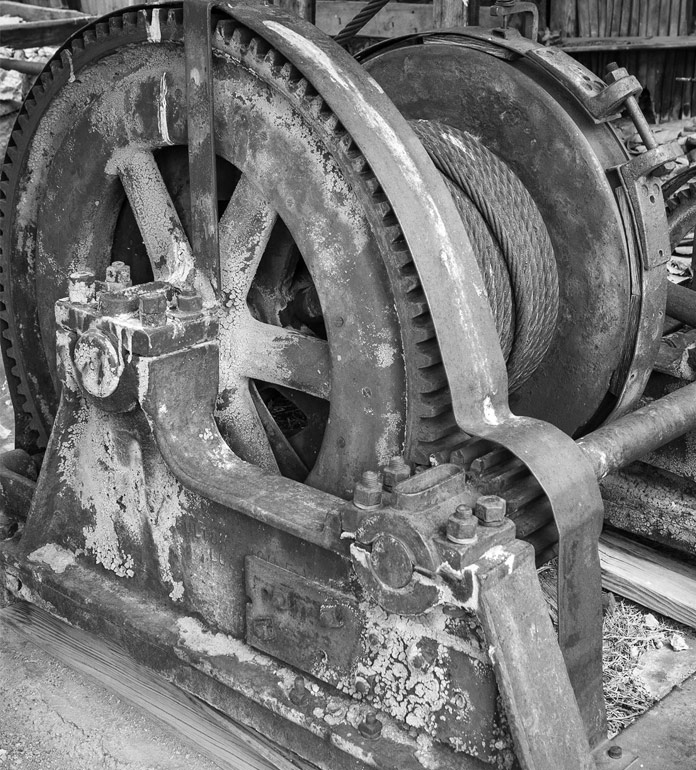
In 1820's Germany, the first systematic study of metal fatigue was being performed on mine cart cable hoists chains. It’s here that repetitive, cyclical, and light loading was observed to result in failure. In this sense, it was as though the chain was tired (or “fatigued”). As observed then and can be observed now, metals subjected to cyclical stresses and strains will develop cracks and fractures over many repetitions, limiting their operating lifetimes.
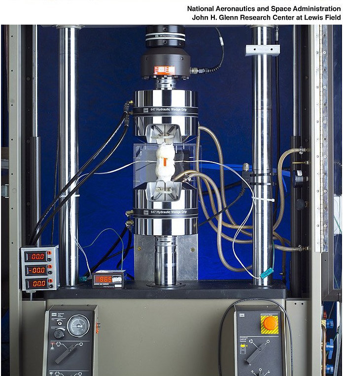
In modern day precision automation tools using direct drive positioning stages with mechanical bearings, the same concerns apply to rolling contact fatigue resulting in material damage to the bearings, usually exhibited by fatigue flaking in the raceway or rolling elements. The optimization of bearing life is partially an exercise in materials, including the use of hardened bearing steel (with rolling contact fatigue and corrosion resistance), proper lubricant chemistry as well as optimized integration, environmental conditions, preloading and correct relative sizing, tolerancing of coupled surfaces, and layout for loading.

A Brief Quantitative Look at Bearing Life
To understand how bearing life is quantified in a “million-mile” stage design, we’ll use the V-817 Linear Motor Stage Series as an example. To start, it is important for the type of bearings used in the V-817 to understand the equation that governs bearing life of this type:
L=50*(C/(fw*P))3
Where:
L= Bearing Rated Life
C= Basic Dynamic Load Rating
P= Dynamic Equivalent Load
Fw=Load Factor
*Courtesy of IKO Bearing
C is an empirical constant specific to the bearing, statistical in nature that defines under what load the bearing can reproducibly achieve an operating life of 50,000 km. Naturally, the larger this value, the longer the rated life under a lower specific applied load condition.
P is a value intended to be representative of a single applied load operated continuously such that it is representative of the various loads that may be acting over time on the bearing that would produce the same estimated lifetime.
Fw is the load factor that is applied based on the operating environment. In high vibration or shock inducing environments, this value is greater than 1 (and as high as 3). In quiet environments, this value is typically 1-1.2 (optimal).
The main takeaway of the above equation is the cubic relation of lifetime and load – reduce your load by 50% and bearing life increases by 800%. This knowledge can be decisive when selecting the right stage for the job. A stage with twice the required load capacity will last a lot longer.
Anatomy of a Million Mile Linear Translation Stage
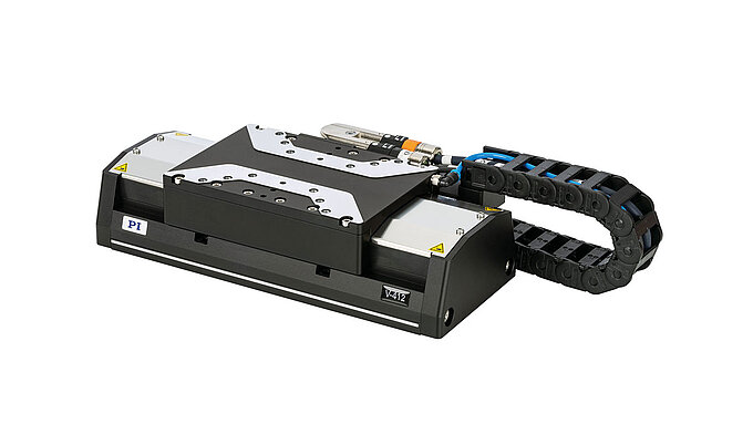
The V-817 linear translation stage uses precision truck and rail bearings with recirculating balls. The dual rail configuration is spaced such that the carriage is supported on the corners in rectangular arrangement intended to spread the load evenly/equally on all four trucks minimizing moment loads. This bearing type is fully supported as well over full travel unlike other bearing types, minimizing moment loads near travel ends.
The bearings of the V-817 positioning stage have a Basic Dynamic Load Rating of 1330 N (or ~135 kg, Normal applied) for each rolling element. In a normal applied load situation such that any CG offset is approximately zero and each rolling element carries 1/4th of the load without moment loads, the Dynamic Load Rating is effectively >500 kg. The V-817 stage is rated for 60 kg loads to guarantee extended operating life while considering use cases with different loading scenarios.
A common term for precision motion systems is “moving mass”. This is the applied load to the bearings that requires moving and typically includes an inherent attribute of the stage (carriage coupled to bearings) along with applied load on carriage. In the V-817 case, the moving mass is approximately 2.2 kg. The payload weight is a function of application requirements, but 10 kg wouldn’t be atypical. The total moving mass is then approximately 12 kg. In this simple example, let us consider the CG of the applied payload is centered and moments loads, approximately zero.
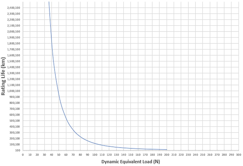
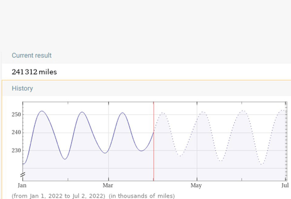
Each rolling element in the dual rail, four trucks arrangement of the V-817 linear translation table carries a load of 3 kg (or 29.4 N, applied) in this scenario with weight distributed evenly. When referenced against the rated life/load curve for the bearings shown below (based on equation above), we observe a rating life of approximately 4.4 Million km or 2.7 Million miles. Putting this in context, the cyclical distance to the moon ranges typically around 240 thousand miles and the stage could theoretically make 10 trips without fatigue failure.
Your Mileage May Vary
The above considerations indicate what is achievable under ideal conditions with a centered load. A cantilevered mass will induce torque and increase loads on individual bearings. Additionally, for highly dynamic applications, the center of gravity should be kept as low as possible to reduce moment loads during acceleration / deceleration. In motion control as with performance cars, the importance of a low CG design is inversely proportional to the demands on dynamics. Performance car manufacturers often run accelerated life tests with their products on the Nürburgring Nordschleife, a track that puts a maximum amount of stress on all mechanical components. And while most vehicles would not even last 10,000 miles running flat out there, 100,000 miles under regular use conditions are no problem at all. There is no Nürburgring test for precision motion stages, but centering the load, removing unnecessary material from mounting hardware, and dropping the center of gravity can pay big dividends on lifetime in 24/7 automation.
Multi-Axis Assemblies: Why a Wide Base is Better
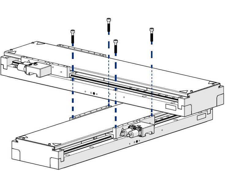
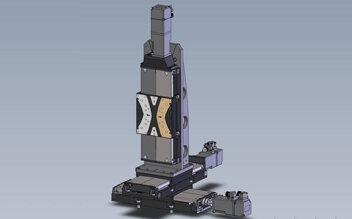
The V-817 series linear stages are often made into XY or XYZ Motion Tables (stacked/aligned). In this configuration, the bottom axis carries the upper axis plus payload. Here, a wide base, especially on the lower stage, will not only improve the geometric performance (in terms of straightness, flatness, pitch, yaw, and roll) of the XY-table but also increase the bearing lifetime, by reducing the moment loads.

Other Configurations for XY Motion
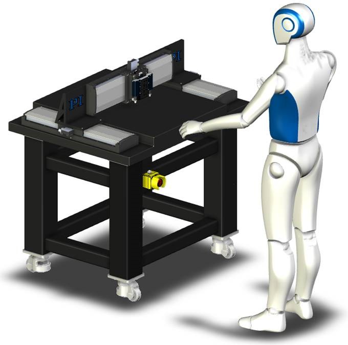
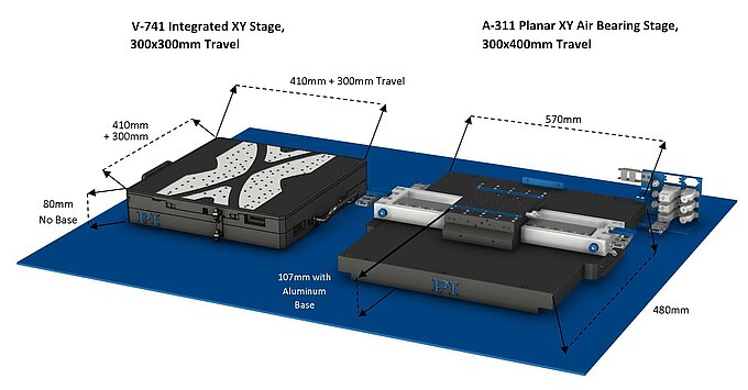
For motion requirements with extended Y-axis travel, a simple XY stage stack is not the best answer. Two parallel stages on the X-axis can be used or a split bridge design or gantry system.
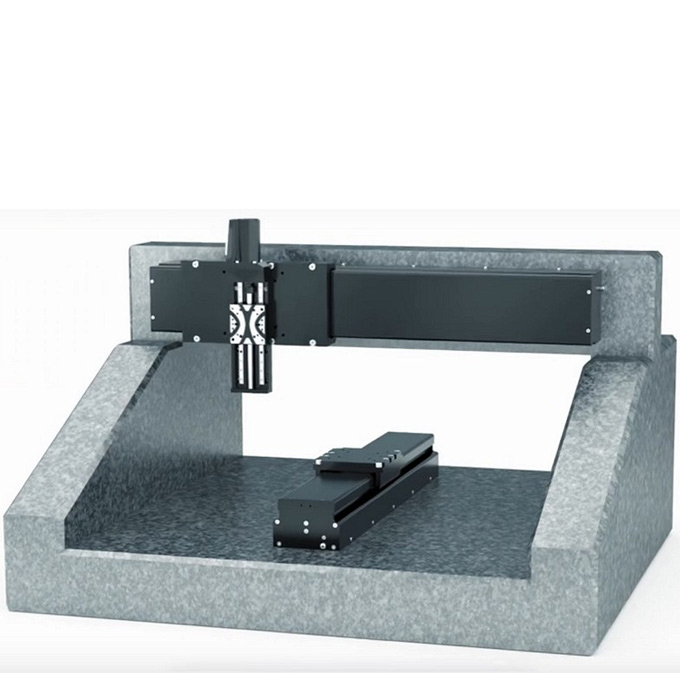
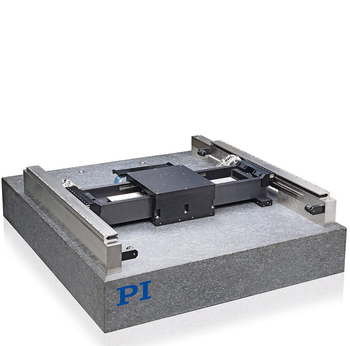
Another way to produce two-dimensional motion is explained in this blog post on R-theta stages based on polar coordinates.
A Final Word
As with any idealized case, there are several factors to consider practically in real-world implementation and expectations. The bearings require proper lubrication, protection from contaminants and debris, temperature cycling and thermal influences are impactful as well as shocks, vibrations and other dynamics that influence stress/strain and associated accelerated rolling fatigue related failures.

The Moon is not Enough?
If travel distances to the moon are not enough for your precision automation application, consider air bearing stages. In contrast to mechanical bearings, air bearings are free from friction, wear, and lubrication is no longer an issue.
Blog Categories
- Aero-Space
- Air Bearing Stages, Components, Systems
- Astronomy
- Automation, Nano-Automation
- Beamline Instrumentation
- Bio-Medical
- Hexapods
- Imaging & Microscopy
- Laser Machining, Processing
- Linear Actuators
- Linear Motor, Positioning System
- Metrology
- Microscopy
- Motorized Precision Positioners
- Multi-Axis Motion
- Nanopositioning
- Photonics
- Piezo Actuators, Motors
- Piezo Mechanics
- Piezo Transducers / Sensors
- Precision Machining
- Semicon
- Software Tools
- UHV Positioning Stage
- Voice Coil Linear Actuator
- X-Ray Spectroscopy


