Programming ACS Motion Controllers with LabVIEW (Elegant and Easy)
Adding more Functionality to the Ethercat-based ACS Controllers
The goal of this sample program is to show the elegant and easy way to program ACS-based motion controllers from PI with LabVIEW. We will walk you through first connection, simple communication with feedback, and then closing the connection in a way that can be the seed for application specific development.
As a part of the approach, we will also present using LabVIEW with ActiveX Automation (using an assembly) and simple connection and programming of the ACS motion simulator. PI / ACS and LabVIEW are an excellent combination that can unlock world-leading precision automation capability.
1. Make sure that the ACS ADK Suite is installed on the PC with LabVIEW. Contact PI, if you need to download.
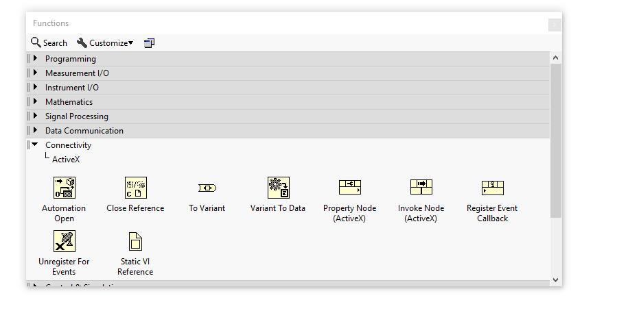
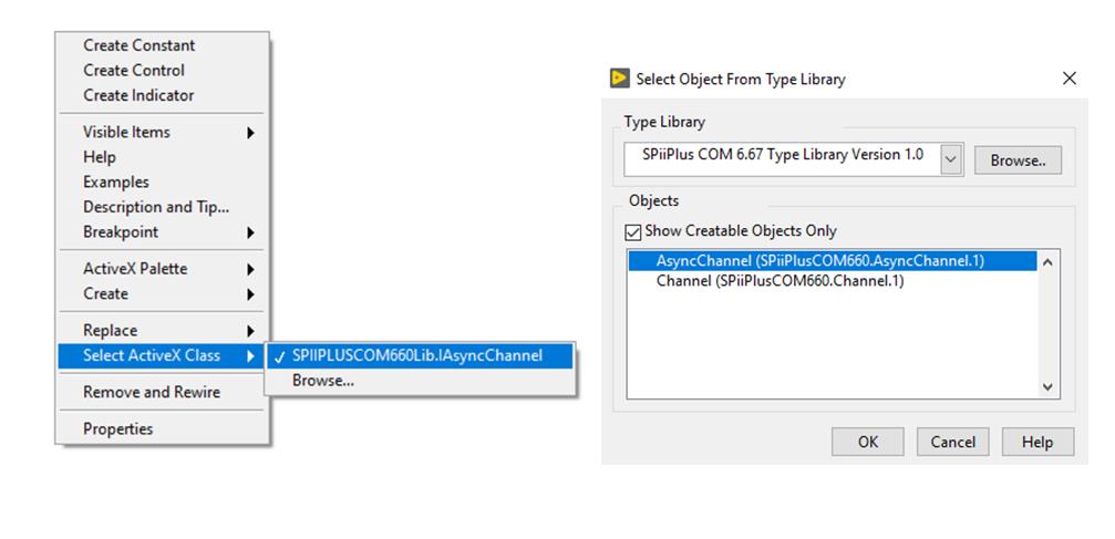
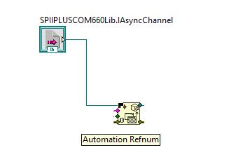
2. To begin, we will be using an ActiveX Server. ActiveX is based on COM (Component Object Model) technologies that allow you to reuse code and link programs together. LabVIEW, in our case, will act as an Automation Client with a program structure that follows Automation Open->Invoke Methods->Automation Close. You will see this practically in effect in the example outlined below.
3. To use LabVIEW in this way, we must register our ActiveX Server (DLL) provided in the ACS ADK Suite.
4. Type CMD in the Windows Search box to get a command prompt. Here you can register the DLL with the command below – please note your path may be different – check your install path and replace path as necessary. Also note: the user in this case should have administrator rights.
regsvr32 “C:\Program Files (x86)\ACS Motion Control\CommonFiles\SPiiPlusCOM660_x86.dll”
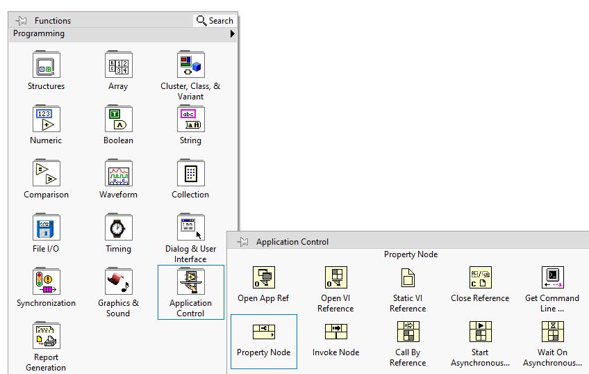
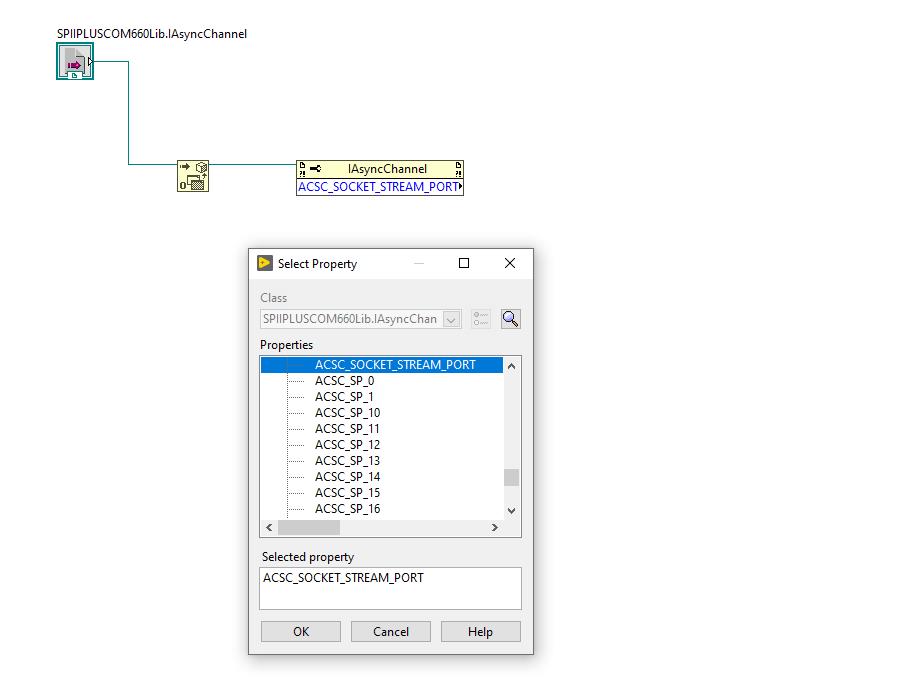
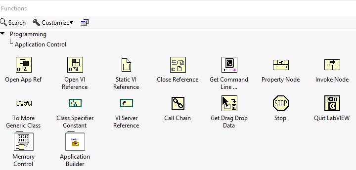
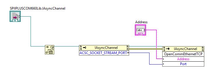
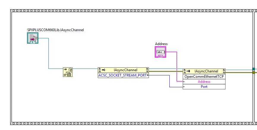
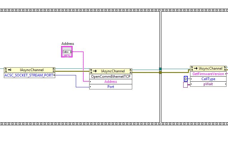
11. In the next step, we select “invoke node” (Functions-> Application Control->Invoke Node) and wire reference out on the property node to the invoke node reference input. When this is connected, the method can be selected (this shows how LabVIEW works as an automation client).
Here we select OpenCommEthernetTCP to establish communication. This function has two inputs (Address and Port). Here, we make a String Control (for IP Address) and run our property node PORT output to the Port input.
12. Once this is connected, we can open a socket and communicate with the controller. At this point we can either communicate with the motion simulator or with a connected controller. We’ll deal with each case separately below:
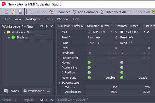
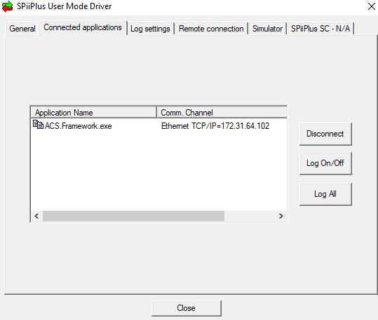
a. Simulator: The simulator requires the ACS MMI to be open and simulator connected. Once this is done, we can also check the simulator IP address.
i. Checking the IP address is done easily-open the ACS MMI and note the Simulator is there by default.
b. Connected Controller:
i. The default IP address for the controller will be 10.0.0.100.
1. The host PC should have a compatible IP Address, namely 10.0.0.xxx (where xxx≠100).
2. From here, the IP Address of the controller can be used in the “IP Address” string control.
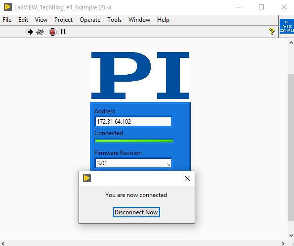
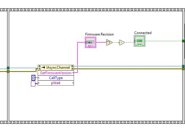
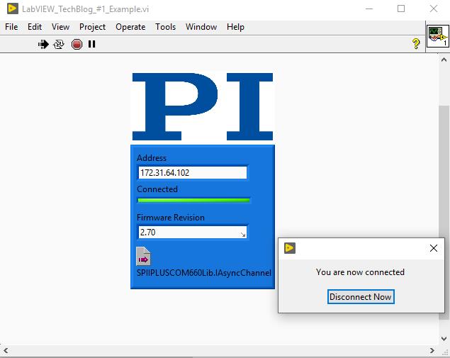
15. In the second frame, we’ll make a quick program to check Firmware Revision and indicate connection status.
As before, we use an invoke node (Functions-> Application Control->Invoke Node) and wire the reference out on the OpenCommEthernetTCP Method to the reference in on the invoke node. Once this is done, we can select the method.
In this case, we select GetFirmwareRevision. Here, we see two inputs: CallType and pWait. CallType can be wired to an empty constant (right click on the input and select create constant)-do the same for pWait, but set constant value to 0.
17. You can now wire a string control to the output of the GetFirmwareVersion Method. Here, we can use feedback to verify we are connected and getting proper responses from the Motion Simulator/Controller. To do this, we can wire a string indicator to the output of GetFirmwareVersion.
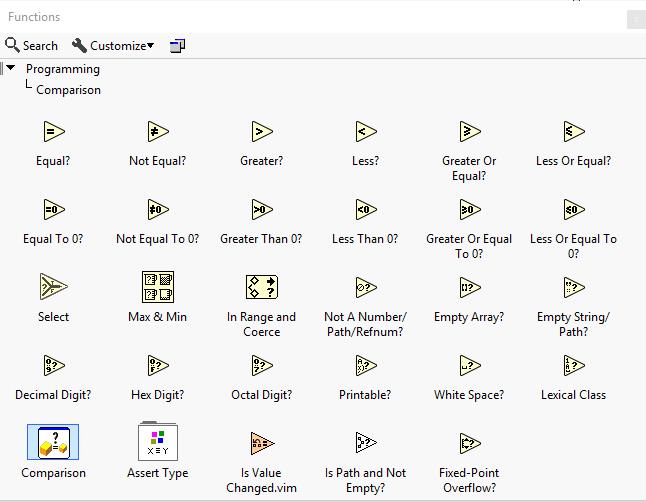
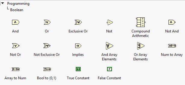
Then, we can check if there is an empty string being returned by adding “Empty String/Path?” .vi (Functions->Programming->Comparison). We then wire a Boolean Not (to negate the True/False output). In this case, an empty string will indicate True (when we want a non-empty string to indicate True).
We can then add a Boolean Indicator on the front panel (to light up when verify connected with proper feedback from the controller).
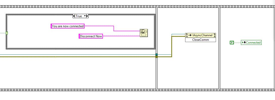
18. Finally, in a new frame (right click on the sequence structure and add a frame after), we add a Case Structure with Dialog Boxes to confirm connection status. The Case Structure uses a Boolean Indicator selecting the case. If True, the message confirms connected. If false, the message says check IP Address. Now we need to close the connection. Finally, add a frame and connect another invoke node, select the CloseComm method to close the socket we had opened. In your last frame, you need to set the Connected indicator to false (disconnected). In the block diagram below, a local variable is created from connected indicator to avoid additional wiring.
Blog Categories
- Aero-Space
- Air Bearing Stages, Components, Systems
- Astronomy
- Automation, Nano-Automation
- Beamline Instrumentation
- Bio-Medical
- Hexapods
- Imaging & Microscopy
- Laser Machining, Processing
- Linear Actuators
- Linear Motor, Positioning System
- Metrology
- Microscopy
- Motorized Precision Positioners
- Multi-Axis Motion
- Nanopositioning
- Photonics
- Piezo Actuators, Motors
- Piezo Mechanics
- Piezo Transducers / Sensors
- Precision Machining
- Semicon
- Software Tools
- UHV Positioning Stage
- Voice Coil Linear Actuator
- X-Ray Spectroscopy


